Mitsubishi Eclipse. Manual - part 475


  Index      Mitsubishi     Mitsubishi Eclipse - service repair manual 2004 year


Search            


Content   ..  473  474  475  476   ..


Mitsubishi Eclipse. Manual - part 475


MULTIPORT FUEL INJECTION (MFI) DIAGNOSIS

TSB Revision

MULTIPORT FUEL INJECTION (MFI) <3.0L>

13B-443

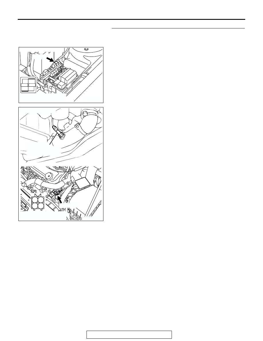
STEP 9. Check for harness damage between MFI relay 
connector A-18X (terminal No. 4) and left bank heated 
oxygen sensor (rear) connector B-23 (terminal No. 1).
Q: Is the harness wire in good condition?

YES : Go to Step 10.
NO :  Repair it. Then go to Step 12.

AK300454

2

1

3

4

CONNECTOR: A-18X

AB

A-18X

HARNESS CONNECTOR:
COMPONENT SIDE

AK300410

1

2

3

4

LEFT BANK 
HEATED OXYGEN
SENSOR (REAR)

CONNECTOR: B-23

AB

B-23 (GR)

HARNESS CONNECTOR:
COMPONENT SIDE

MULTIPORT FUEL INJECTION (MFI) DIAGNOSIS

TSB Revision

MULTIPORT FUEL INJECTION (MFI) <3.0L>

13B-444

STEP 10. Check for harness damage between left bank 
heated oxygen sensor (rear) connector B-23 (terminal No. 
3) and ECM connector C-51 (terminal No. 26) <M/T> or PCM 
connector C-52 (terminal No. 26) <A/T>.
Q: Is the harness wire in good condition?

YES : Go to Step 11.
NO :  Repair it. Then go to Step 12.

AK300410

1

2

3

4

LEFT BANK 
HEATED OXYGEN
SENSOR (REAR)

CONNECTOR: B-23

AB

B-23 (GR)

HARNESS CONNECTOR:
COMPONENT SIDE

AK300458

2

3

4

5

6

7

8

9

11

12

13

14

15

16

17

18

19

20

30

21

22

23

24

25

26

27

28

29

31

32

33

34

35

1

10

CONNECTOR: C-52 <A/T>

C-52 (GR)

AB

HARNESS CONNECTOR:
COMPONENT SIDE

MULTIPORT FUEL INJECTION (MFI) DIAGNOSIS

TSB Revision

MULTIPORT FUEL INJECTION (MFI) <3.0L>

13B-445

STEP 11. Check the trouble symptoms.
(1) Carry out a test drive with the drive cycle pattern. Refer to 

Diagnostic Function 

− OBD-II Drive Cycle − Procedure 6 − 

Other Monitor 

P.13B-7

.

(2) Check the diagnostic trouble code (DTC).
Q: Is DTC P0161 set?

YES : Replace the ECM or PCM. Then go to Step 12.
NO :  It can be assumed that this malfunction is intermittent. 

Refer to GROUP 00, How to Use Troubleshooting/ 
Inspection Service Points 

P.00-6

.

STEP 12. Test the OBD-II drive cycle.
(1) Carry out a test drive with the drive cycle pattern. Refer to 

Diagnostic Function 

− OBD-II Drive Cycle −Procedure 6 − 

Other Monitor 

P.13B-7

.

(2) Check the diagnostic trouble code (DTC).
Q: Is DTC P0161 set?

YES : Retry the troubleshooting.
NO :  The inspection is complete.

DTC P0171: System too Lean (bank 1)

.

System too Lean (bank 1) Circuit

• Refer to DTC P0201, P0203, P0205 − Injector 

Circuit 

P.13B-510

.

.

CIRCUIT OPERATION

• Refer to DTC P0201, P0203, P0205 − Injector 

Circuit 

P.13B-510

.

.

TECHNICAL DESCRIPTION

• If a malfunction occurs in the fuel system, the fuel 

trim value becomes too large.

• The ECM <M/T> or PCM <A/T> checks whether 

the fuel trim value is within a specified range.

.

DESCRIPTIONS OF MONITOR METHODS
Right bank air/fuel learning value (long time fuel trim) 

and air/fuel feedback integral value (short time 
fuel trim) are too lean.

.

MONITOR EXECUTION
Continuous

.

AK300443

2

3

4

5

6

7

8

9

11

12

13

14

15

16

17

18

19

20

30

21

22

23

24

25

26

27

28

29

31

32

33

34

35

1

10

CONNECTOR: C-51 <M/T>

C-51 (GR)

AB

HARNESS CONNECTOR:
COMPONENT SIDE

MULTIPORT FUEL INJECTION (MFI) DIAGNOSIS

TSB Revision

MULTIPORT FUEL INJECTION (MFI) <3.0L>

13B-446

MONITOR EXECUTION CONDITIONS (Other 
monitor and Sensor)

Other Monitor (There is no temporary DTC stored 

in memory for the item monitored below)

• Misfire monitor

Sensor (The sensor below is determined to be 

normal)

• Volume airflow sensor

• Engine coolant temperature sensor

• Intake air temperature sensor

• Barometric pressure sensor

• Throttle position sensor

.

DTC SET CONDITIONS

Logic Flow Chart

.

Check Conditions

• Engine coolant temperature is lower than approx-

imately 100

°C (212°F) when the engine is 

started.

• Intake air temperature is lower than 60°C (140°F) 

when the engine is started.

• Under the closed loop air/fuel ratio control.

• Engine coolant temperature is higher than 77°C 

(171

°F).

• Volume airflow sensor output frequency is 75 Hz 

or more.

K

LRN

: LONG-TERM TRIM

K

I

: SHORT-TERM TRIM

K0 : MAXIMUM LIMIT OF LONG-TERM TRIM
K1 : MAXIMUM LIMIT OF SHORT-TERM TRIM
K2 : MINIMUM LIMIT OF LONG-TERM TRIM
K3 : MINIMUM LIMIT OF SHORT-TERM TRIM

START

MONITORING

CONDITIONS

END

NO

NO

NO

NO

NO

NO

YES

YES

YES

YES

YES

YES

K

LRN

 > K0

MALFUNCTION

GOOD

K

LRN

 < K2

K

I

< K3

K

I

> K1

CONTINUOUS FAILURE

FOR 5secs

AK204050


Content   ..  473  474  475  476   ..