Mitsubishi Eclipse. Manual - part 463
MULTIPORT FUEL INJECTION (MFI) DIAGNOSIS
TSB Revision
MULTIPORT FUEL INJECTION (MFI) <3.0L>
13B-395
DTC SET CONDITIONS
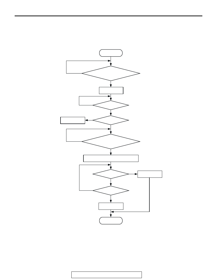
Logic Flow Chart
.
Check Conditions
• 3 minutes or more have passed since the starting
sequence was completed.
• Left bank heated oxygen sensor (rear) signal volt-
age has continued to be 0.15 volt or lower.
• Engine coolant temperature is higher than 76°C
(169
°F).
• Engine speed is higher than 1,200 r/min.
• Volumetric efficiency is higher than 25 percent.
• Monitoring time: 7 seconds.
START
V
F
> =4.5V
2secs HAS PASSED
YES
YES
YES
NO
NO
NO
MALFUNCTION
MONITORING
CONDITIONS
YES
NO
MONITORING
CONDITIONS
+5V ON
AK301440
V
F
< 0.15V
10secs HAS PASSED
YES
YES
NO
NO
END
MALFUNCTION
GOOD
MODULATE A/F CONDITION TO RICH