Mitsubishi Eclipse. Manual - part 452
MULTIPORT FUEL INJECTION (MFI) DIAGNOSIS
TSB Revision
MULTIPORT FUEL INJECTION (MFI) <3.0L>
13B-351
.
CIRCUIT OPERATION
• A voltage corresponding to the oxygen concen-
tration in the exhaust gas is sent to the ECM (ter-
minal No. 71) <M/T> or PCM (terminal No. 71)
<A/T> from the output terminal (terminal No. 4) of
the left bank heated oxygen sensor (front).
• Terminal No. 2 of the left bank heated oxygen
sensor (front) is grounded with ECM (terminal
No. 49) <M/T> or PCM (terminal No. 57) <A/T>.
.
TECHNICAL DESCRIPTION
• The left bank heated oxygen sensor (front)
detects the concentration of oxygen in the
exhaust gas; it converts that data to voltage, and
sends it to the ECM <M/T> or PCM <A/T>.
• When the left bank heated oxygen sensor (front)
begins to deteriorate, the heated oxygen sensor
signal response deteriorates also.
• The ECM <M/T> or PCM <A/T> varies the air/fuel
mixture to make it leaner and richer, and checks
the response speed of the left bank heated oxy-
gen sensor (front). In addition, the ECM <M/T> or
PCM <A/T> also checks for an open circuit in the
left bank heated oxygen sensor (front) output
line.
.
DESCRIPTIONS OF MONITOR METHODS
Left bank heated oxygen sensor (front) output volt-
age stays low when air/fuel ratio is forced to be
rich. The above procedure is repeated when oxy-
gen sensor is inactive.
.
MONITOR EXECUTION
Continuous
.
MONITOR EXECUTION CONDITIONS (Other
monitor and Sensor)
Other Monitor (There is no temporary DTC stored
in memory for the item monitored below)
• Heated oxygen sensor heater (front) monitor
• Misfire monitor
• Fuel system monitor
Sensor (The sensor below is determined to be
normal)
• Volume airflow sensor
• Engine coolant temperature sensor
• Intake air temperature sensor
• Barometric pressure sensor
• Throttle position sensor
.
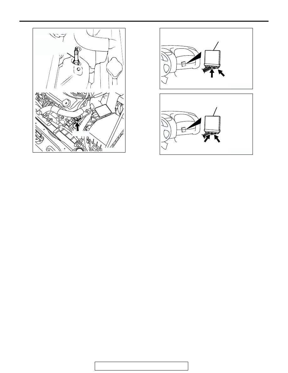
AK300061
LEFT BANK
HEATED OXYGEN
SENSOR (FRONT)
CONNECTOR: B-24
AB
B-24 (B)
AK300091
CONNECTORS: C-58, C-62 <M/T>
ECM
AD
C-58 (GR)
C-62 (GR)
AK300244
CONNECTORS: C-55, C-59 <A/T>
AD
PCM
C-55 (GR)
C-59 (GR)