Mitsubishi Eclipse. Manual - part 449


  Index      Mitsubishi     Mitsubishi Eclipse - service repair manual 2004 year


Search            


Content   ..  447  448  449  450   ..


Mitsubishi Eclipse. Manual - part 449


MULTIPORT FUEL INJECTION (MFI) DIAGNOSIS

TSB Revision

MULTIPORT FUEL INJECTION (MFI) <3.0L>

13B-339

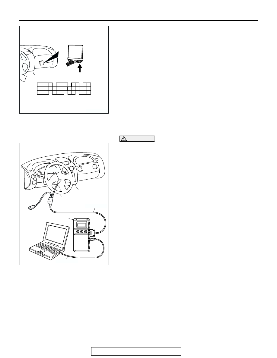
STEP 5. Using scan tool MB991958, check data list item 11: 
Heated Oxygen Sensor Bank 2, Sensor 1 (left front).

CAUTION

To prevent damage to scan tool MB991958, always turn the 
ignition switch to the "LOCK" (OFF) position before con-
necting or disconnecting scan tool MB991958.
(1) Connect scan tool MB991958 to the data link connector.
(2) Start the engine and run at idle.
(3) Set scan tool MB991958 to the data reading mode for item 

11, Heated Oxygen Sensor Bank 2, Sensor 1 (left front).

• Warming up the engine. When the engine is revved, the 

output voltage should be 0.6 to 1.0 volt.

• Warming up the engine. When the engine is idling, the 

output voltage should repeat 0.4 volt and 0.6 to 1.0 volt 
alternately.

(4) Turn the ignition switch to the "LOCK" (OFF) position.
Q: Is the sensor operating properly?

YES : It can be assumed that this malfunction is intermittent. 

Refer to GROUP 00, How to Use Troubleshooting/ 
Inspection Service Points 

P.00-6

.

NO :  Replace the ECM or PCM. Then go to Step 15.

AK300445

80

87

81

94

85

82

84

93

86

98

99

74

92

73

83

88

91

95

97 96

100

89

78

71

90

76

77

75

72
79

CONNECTOR: C-62 <M/T>

C-62 (GR)

AB

HARNESS CONNECTOR:
COMPONENT SIDE

AK300810

AB

MB991911

16-PIN

MB991827

MB991824 

MULTIPORT FUEL INJECTION (MFI) DIAGNOSIS

TSB Revision

MULTIPORT FUEL INJECTION (MFI) <3.0L>

13B-340

STEP 6. Check connector B-24 at left bank heated oxygen 
sensor (front) and connector C-62 at ECM <M/T> or 
connector C-59 at PCM <A/T> for damage.
Q: Is the connector in good condition?

YES : Repair harness wire between left bank heated oxygen 

sensor (front) connector B-24 (terminal No. 4) and 
ECM connector C-62 (terminal No. 71) <M/T> or PCM 
connector C-59 (terminal No. 71) <A/T> because of 
open circuit or harness damage. Then go to Step 15.

NO :  Repair or replace it. Refer to GROUP 00E, Harness 

Connector Inspection 

P.00E-2

. Then go to Step 15.

AK300424

1

2

3

4

LEFT BANK 
HEATED OXYGEN
SENSOR (FRONT)

CONNECTOR: B-24

AB

B-24 (B)

HARNESS CONNECTOR:
COMPONENT SIDE

AK300460

98

78

71

88

89

76

77

72
79
91

73
80

74

75

81
92

82

83

93

84

85

94

86

87

95

96

90

97

CONNECTOR: C-59 <A/T>

C-59 (GR)

AB

HARNESS CONNECTOR:
COMPONENT SIDE

MULTIPORT FUEL INJECTION (MFI) DIAGNOSIS

TSB Revision

MULTIPORT FUEL INJECTION (MFI) <3.0L>

13B-341

STEP 7. Check connector B-24 at left bank heated oxygen 
sensor (front) for damage.
Q: Is the connector in good condition?

YES : Go to Step 8.
NO :  Repair or replace it. Refer to GROUP 00E, Harness 

Connector Inspection 

P.00E-2

. Then go to Step 15.

AK300445

80

87

81

94

85

82

84

93

86

98

99

74

92

73

83

88

91

95

97 96

100

89

78

71

90

76

77

75

72
79

CONNECTOR: C-62 <M/T>

C-62 (GR)

AB

HARNESS CONNECTOR:
COMPONENT SIDE

AK300424

1

2

3

4

LEFT BANK 
HEATED OXYGEN
SENSOR (FRONT)

CONNECTOR: B-24

AB

B-24 (B)

HARNESS CONNECTOR:
COMPONENT SIDE

MULTIPORT FUEL INJECTION (MFI) DIAGNOSIS

TSB Revision

MULTIPORT FUEL INJECTION (MFI) <3.0L>

13B-342

STEP 8. Check the continuity at left bank heated oxygen 
sensor (front) harness side connector B-24.
(1) Disconnect the connector B-24 and measure at the harness 

side.

(2) Check for the continuity between terminal No. 2 and 

ground.

• Should be less than 2 ohms.

Q: Is the continuity normal?

YES : Go to Step 11.
NO :  Go to Step 9.

AK300424

1

2

3

4

LEFT BANK 
HEATED OXYGEN
SENSOR (FRONT)

CONNECTOR: B-24

AB

B-24 (B)

HARNESS CONNECTOR:
COMPONENT SIDE

AK000239AT

B-24 HERNESS 
CONNECTOR: 
COMPONENT SIDE

2 1
4 3


Content   ..  447  448  449  450   ..