Mitsubishi Eclipse. Manual - part 418
MULTIPORT FUEL INJECTION (MFI) DIAGNOSIS
TSB Revision
MULTIPORT FUEL INJECTION (MFI) <3.0L>
13B-215
.
CIRCUIT OPERATION
• A voltage corresponding to the oxygen concen-
tration in the exhaust gas is sent to the ECM (ter-
minal No. 72) <M/T> or PCM (terminal No. 72)
<A/T> from the output terminal (terminal No. 4) of
the right bank heated oxygen sensor (front).
• Terminal No. 2 of the right bank heated oxygen
sensor (front) is grounded with ECM (terminal
No. 49) <M/T> or PCM (terminal No. 57) <A/T>.
.
TECHNICAL DESCRIPTION
• The right bank heated oxygen sensor (front)
detects the concentration of oxygen in the
exhaust gas; it converts those data to voltage,
and inputs the resulting signals to the ECM
<M/T> or PCM <A/T>.
• When the right bank heated oxygen sensor
(front) begins to deteriorate, the heated oxygen
sensor signal response becomes poor.
• The ECM <M/T> or PCM <A/T> forcibly varies
the air/fuel mixture to make it leaner and richer,
and checks the response speed of the right bank
heated oxygen sensor (front). In addition, the
ECM <M/T> or PCM <A/T> also checks for an
open circuit in the right bank heated oxygen sen-
sor (front) output line.
.
DESCRIPTIONS OF MONITOR METHODS
Right bank heated oxygen sensor (front) circuit is
switched to 5 volts intentionally when oxygen
sensor output is low, and detects the malfunction
if the output voltage changes to equal or greater
than 4.5 volts. The above procedure is repeated
when oxygen sensor is inactive.
.
MONITOR EXECUTION
Continuous
.
MONITOR EXECUTION CONDITIONS (Other
monitor and Sensor)
Other Monitor (There is no temporary DTC stored
in memory for the item monitored below)
• Heated oxygen sensor heater (front) monitor
• Misfire monitor
• Fuel system monitor
Sensor (The sensor below is determined to be
normal)
• Volume airflow sensor
• Engine coolant temperature sensor
• Intake air temperature sensor
• Barometric pressure sensor
• Throttle position sensor
.
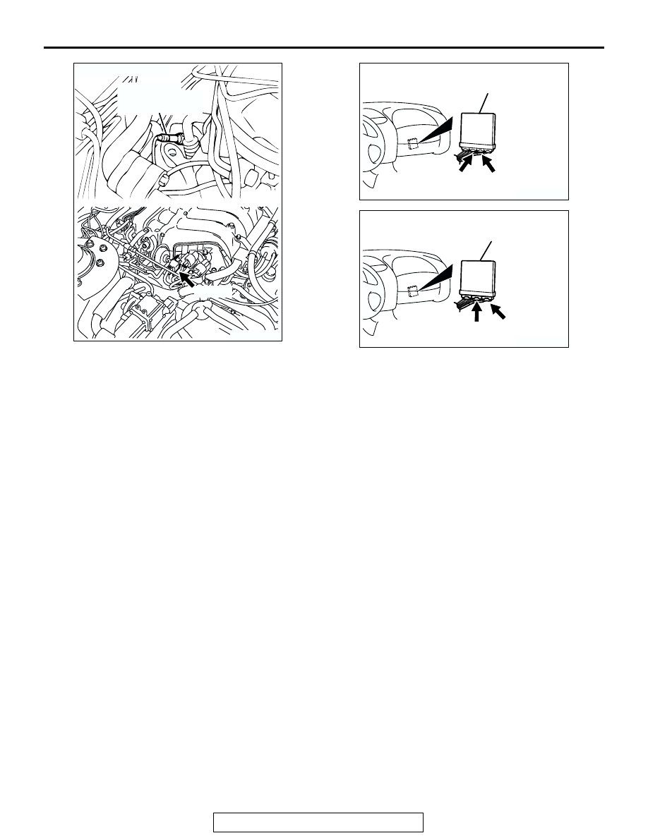
AK300057
RIGHT BANK
HEATED OXYGEN
SENSOR (FRONT)
AB
B-27 (B)
CONNECTOR: B-27
AK300244
CONNECTORS: C-55, C-59 <A/T>
AD
PCM
C-55 (GR)
C-59 (GR)
AK300091
CONNECTORS: C-58, C-62 <M/T>
ECM
AD
C-58 (GR)
C-62 (GR)