Mitsubishi Eclipse. Manual - part 372
MULTIPORT FUEL INJECTION (MFI) DIAGNOSIS
TSB Revision
MULTIPORT FUEL INJECTION (MFI) <3.0L>
13B-31
.
CIRCUIT OPERATION
• The volume airflow sensor power is supplied from
the MFI relay (terminal No. 4), and the ground is
provided on the ECM (terminal No. 34) <M/T> or
PCM (terminal No. 16) <A/T>.
• 5-volt power is applied to the volume airflow sen-
sor output terminal (terminal No. 3) from the ECM
(terminal No. 61) <M/T> or PCM (terminal No. 65)
<A/T>. The volume airflow sensor generates a
pulse signal when the output terminal and ground
are opened/closed (opened/short).
• 6-9 volts power is applied to the PCM (terminal
No. 19) from the volume airflow sensor (terminal
No. 7).
• The PCM (terminal No. 19) controls the airflow
sensror reset signal by turning the power transis-
tor within the PCM to "ON" and "OFF" position.
.
TECHNICAL DESCRIPTION
• While the engine is running, the volume airflow
sensor outputs a pulse signal which corresponds
to the volume of air flow.
• The ECM <M/T> or PCM <A/T> checks whether
the frequency of this signal output by the volume
airflow sensor while the engine is running is at or
above the set value.
• When the throttle position sensor output voltage
is low, the ECM <M/T> or PCM <A/T> causes the
power transistor to be "ON" to send an volume
airflow sensor reset signal to the volume airflow
sensor. In response to the reset signal, the vol-
ume airflow sensor resets the filter circuit and
improves the ability of the volume airflow sensor
to measure the amount of air in a small air intake
region.
.
DESCRIPTIONS OF MONITOR METHODS
Compare load value with volume airflow sensor out-
put voltage.
.
MONITOR EXECUTION
Continuous
.
MONITOR EXECUTION CONDITIONS (Other
monitor and Sensor)
Other Monitor (There is no temporary DTC stored
in memory for the item monitored below)
• Not applicable
Sensor (The sensor below is determined to be
normal)
• Throttle position sensor
.
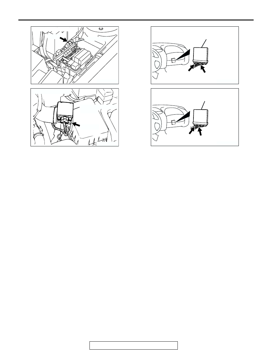
AK300121
MFI RELAY
CONNECTOR: A-18X
AB
A-18X
AK300053
CONNECTOR: B-14
VOLUME AIRFLOW
SENSOR
AB
B-14 (B)
AK300091
CONNECTORS: C-51, C-58 <M/T>
ECM
AB
C-51 (GR)
C-58 (GR)
AK300244
CONNECTORS: C-52, C-55 <A/T>
AB
PCM
C-52 (GR)
C-55 (GR)