Mitsubishi Eclipse. Manual - part 346


  Index      Mitsubishi     Mitsubishi Eclipse - service repair manual 2004 year


Search            


Content   ..  344  345  346  347   ..


Mitsubishi Eclipse. Manual - part 346


MULTIPORT FUEL INJECTION (MFI) DIAGNOSIS

TSB Revision

MULTIPORT FUEL INJECTION (MFI) <2.4L>

13A-877

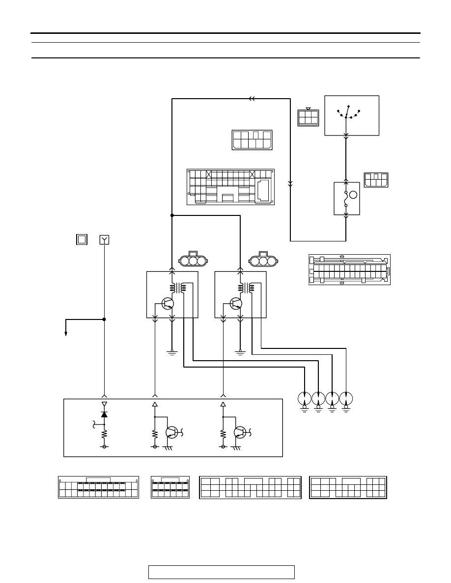
INSPECTION PROCEDURE 33: Ignition Circuit System

AK103265

3

1 2

1 2

1

3

4 5 6

1

GREEN

3

2

4 5 6

7

2

6

3

5

1

4

BLACK-
WHITE

3

8

2

BLA

CK-BLUE

BLA

CK

WHITE-

GREEN

BLA

CK

BLA

CK-

WHITE

BLA

CK-

WHITE

BLA

CK-

WHITE

BLACK-WHITE

BLA

CK-WHITE

LOCK

ACC

IG1

IGNITION
SWITCH

C-87

2

6

10

15

C-89

R

    C-111
MU801331

IG2

IGNITION
COIL 1

IGNITION
COIL 2

      B-16
(MU802053)

      B-21
(MU802053)

4

     C-07
MU801333

JUNCTION
BLOCK

ST

2

2

1

1

3

3

SPARK PLUG

Ignition Circuit

15 16

26 27 28 29

32 33 34

17 18 19 20 21 22 23 24 25

30 31

36 37

35

38

10

11 12 13

1 2 3

4 5 6 7 8 9

14

1

6

4 5

11

10

1213

15

17

16

14

19

18

8 9

7

20

2 3

2122 23 2425 26 27 28

C-108

C-54 <A/T>
(MU803781)

C-50 <A/T>
(MU803784)

C-49 <M/T>
(MU803773)

C-56 <M/T>
(MU803770)

NOTE
*1:ECM connector C-49 <M/T>
*2:ECM connector C-56 <M/T>
*3:PCM connector C-50 <A/T>
*4:PCM connector C-54 <A/T>

1

14

4

19

5

22

6

17

8

15

9

18

7

20

16

2

13

12

23 24 25 26

21

3

10 11

42 43
48 49 50 51 52 53 54 55 56 57

46

45

44

58 59

60 61 62 63

64 65 66

47

41

2

3 4

5 6

7 8

9

11 12 13 14 15 16 17 18 19 20

30

21 22 23

24 25

26 27 28 29

3132 33

34 35

1

10

58

60 61

53

52

51

55

54

56

59

62

57

58
<M/T>*2
43
<A/T>*4

10
<M/T>*1
11
<A/T>*3

23
<M/T>*1
12
<A/T>*3

ENGINE CONTROL
MODULE (ECM) <M/T>
OR
POWERTRAIN CONTROL
MODULE (PCM) <A/T>

WHITE

WHITE

1

ENGINE SPEED
DETECTION
CONNECTOR

1

A-12X

MATER AND
GAUGE

24

10A

MULTIPORT FUEL INJECTION (MFI) DIAGNOSIS

TSB Revision

MULTIPORT FUEL INJECTION (MFI) <2.4L>

13A-878

.

AK300063

CONNECTORS: B-16, B-21

AB

B-21 (GR)

B-16 (GR)

AK300060

ECM

CONNECTORS: C-49, C-56 <M/T>

AJ

C-56 (G)

C-49 (G)

AK300060

PCM

CONNECTORS: C-50, C-54 <A/T>

AO

C-54 (GR)

C-50 (GR)

AK300116

CONNECTOR: C-87

AB

C-87

AK300123

CONNECTOR: C-108

AB

C-108

AK300124

CONNECTOR: C-111

AB

C-111

AK300092

CONNECTOR: C-07

AB

C-07

AK300112

ENGINE SPEED 
DETECTION 
CONNECTOR

CONNECTOR: A-12X

AB

A-12X

AK300118

CONNECTOR: C-89

AC

C-89

MULTIPORT FUEL INJECTION (MFI) DIAGNOSIS

TSB Revision

MULTIPORT FUEL INJECTION (MFI) <2.4L>

13A-879

CIRCUIT OPERATION

• The ignition coil is energized by Battery positive 

voltage from the ignition switch.

• When the ECM <M/T> or PCM <A/T> turns off its 

internal power transistor, battery positive voltage 
is applied to the ignition power transistor (termi-
nal No. 3) inside the ignition coil, causing the igni-
tion power transistor to be turned on.

• If the ignition power transistor is turned on, the 

primary circuit of the ignition coil is energized by 
grounding the ignition coil through terminal No. 2, 
causing the primary current to flow to the ignition 
coil.

.

TROUBLESHOOTING HINTS (The most likely 
causes for this case: )

• Malfunction of the ignition coil.

• Malfunction of the ignition power transistor.

• Improper connector contact, open circuit or 

short-circuited harness wire.

• Malfunction of the ECM <M/T> or PCM <A/T>.

DIAGNOSIS

STEP 1. Check the ignition coil.
Refer to GROUP 16, Ignition System 

− On-vehicle service − 

Ignition Coil Check 

P.16-37

.

Q: Are there any abnormalities?

YES : Go to Step 2.
NO :  Replace the ignition coil. Then confirm that the 

malfunction symptom is eliminated.

STEP 2. Check harness connector B-16, B-21 at ignition 
coil for damage.
Q: Is the harness connector in good condition?

YES : Go to Step 3.
NO :  Repair or replace it. Refer to GROUP 00E, Harness 

Connector Inspection 

P.00E-2

. Then confirm that the 

malfunction symptom is eliminated.

AK300742

1

2

3

CONNECTORS: B-16, B-21

AB

B-21 (GR)

B-16 (GR)

HARNESS CONNECTOR:
COMPONENT SIDE

MULTIPORT FUEL INJECTION (MFI) DIAGNOSIS

TSB Revision

MULTIPORT FUEL INJECTION (MFI) <2.4L>

13A-880

STEP 3. Measure the power supply voltage at ignition coil 
connectors B-16, B-21.
(1) Disconnect the connector B-16, B-21 and measure at the 

harness side.

(2) Turn the ignition switch to the "ON" position.

(3) Measure the voltage between terminal No. 1 and ground.

• Voltage should be battery positive voltage.

(4) Turn the ignition switch to the "LOCK" (OFF) position.
Q: Is battery positive voltage (approximately 12 volts) 

present?
YES : 
Go to Step 4.
NO :  Check the connector C-07, C-89, C-108 and C-111 at 

intermediate connectors for damage, and repair or 
replace as required. Refer to GROUP 00E, Harness 
Connector Inspection 

P.00E-2

. If intermediate 

connector are in good condition, repair harness wire 
between ignition switch connectors C-87 (terminal No. 
2) and ignition coil connectors B-16, B-21 (terminals 
No. 1) because of open circuit. Then confirm that the 
malfunction symptom is eliminated.

STEP 4. Check the circuit at ignition coil harness side 
connector B-16, B-21.
(1) Disconnect the connectors B-16, B-21 and measure at the 

harness side.

(2) Engine cranking.

(3) Measure the voltage between terminal No. 3 and ground.

• Voltage should be 0.3 and 3.0 volts.

(4) Turn the ignition switch to the "LOCK" (OFF) position.
Q: Is the measured voltage between 0.3 and 3.0 volts?

YES : Go to Step 7.
NO :  Go to Step 5.

AK300742

1

2

3

CONNECTORS: B-16, B-21

AB

B-21 (GR)

B-16 (GR)

HARNESS CONNECTOR:
COMPONENT SIDE

AK000414AJ

B-16, B-21 HARNESS 
CONNECTORS: 
COMPONENT SIDE

1

2

3

AK300742

1

2

3

CONNECTORS: B-16, B-21

AB

B-21 (GR)

B-16 (GR)

HARNESS CONNECTOR:
COMPONENT SIDE

AK000415 AK

B-16, B-21 HARNESS 
CONNECTORS: 
COMPONENT SIDE

1

2

3


Content   ..  344  345  346  347   ..