Mitsubishi Eclipse. Manual - part 325


  Index      Mitsubishi     Mitsubishi Eclipse - service repair manual 2004 year


Search            


Content   ..  323  324  325  326   ..


Mitsubishi Eclipse. Manual - part 325


MULTIPORT FUEL INJECTION (MFI) DIAGNOSIS

TSB Revision

MULTIPORT FUEL INJECTION (MFI) <2.4L>

13A-793

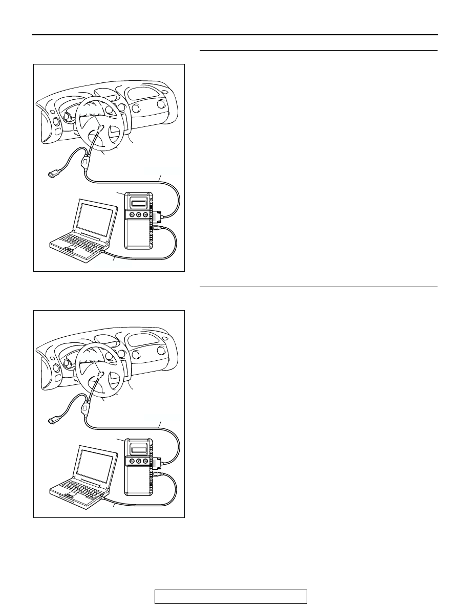
STEP 4. Using scan tool MB991958, check actuator test.
(1) Turn the ignition switch to the "ON" position.
(2) Check the following items in the actuator test. Refer to, 

Actuator Test Reference Table 

P.13A-903

.

a. Item 10: EGR Vacuum Regulator Solenoid Valve.

(3) Turn the ignition switch to the "LOCK" (OFF) position.
Q: Is the actuator operating properly?

YES : Go to Step 5.
NO :  Repair or replace. Then confirm that the malfunction 

symptom is eliminated.

STEP 5. Using scan tool MB991958, check data list item 45: 
Idle Air Control Position.
(1) Start the engine and run at idle.
(2) Set scan tool MB991958 to the data reading mode for item 

45, Idle Air Control Position.

a. The idle air control motor should drop to the 0 

− 2 posi-

tion during deceleration (from 1,000 r/min or more).

(3) Turn the ignition switch to the "LOCK" (OFF) position.
Q: Is the actuator operation properly?

YES : Check the following items, and repair, replace or 

clean the defective sections.

a. Check the ignition coil, spark plugs, spark plug 

cables.

b. Check the throttle valve area.

Then confirm that the malfunction symptom is 

eliminated.

NO :  Refer to, DTC P0500 

− Vehicle Speed Sensor 

<M/T>

P.13A-612

  or refer to GROUP 23A, Automatic 

Transaxle Diagnosis 

− Diagnostic Trouble Code 

Procedures 

− DTC 23 Output Shaft Speed Sensor 

System <A/T>

P.23A-131

 .

AK300810

AB

MB991911

16-PIN

MB991827

MB991824 

AK300810

AB

MB991911

16-PIN

MB991827

MB991824 

MULTIPORT FUEL INJECTION (MFI) DIAGNOSIS

TSB Revision

MULTIPORT FUEL INJECTION (MFI) <2.4L>

13A-794

INSPECTION PROCEDURE 15: Hesitation, sag or stumble.

.

COMMENT

• In cases such as the above, the ignition system, 

air/fuel mixture or compression pressure may be 
defective.

.

TROUBLESHOOTING HINTS (The most likely 
causes for this case: )

• Malfunction of the ignition system.

• Malfunction of air/fuel ratio control system.

• Malfunction of the fuel supply system.

• Malfunction of the EGR vacuum regulator sole-

noid valve system.

• Poor compression pressure.

DIAGNOSIS

Required Special Tools:

• MB991958 (MUT-III Sub Assembly)

• MB991824: V.C.I.

• MB991827: USB Cable

• MB991911: Main Harness B

STEP 1. Using scan tool MB991958, read the diagnostic 
trouble code (DTC).

CAUTION

To prevent damage to scan tool MB991958, always turn the 
ignition switch to the "LOCK" (OFF) position before con-
necting or disconnecting scan tool MB991958.
(1) Connect scan tool MB991958 to the data link connector.
(2) Turn the ignition switch to the "ON" position.
(3) Read the DTC.
(4) Turn the ignition switch to the "LOCK" (OFF) position.
Q: Is DTC set?

YES : Refer to, Diagnostic Trouble Code Chart 

P.13A-24

.

NO :  Go to Step 2.

AK300810

AB

MB991911

16-PIN

MB991827

MB991824 

MULTIPORT FUEL INJECTION (MFI) DIAGNOSIS

TSB Revision

MULTIPORT FUEL INJECTION (MFI) <2.4L>

13A-795

STEP 2. Using scan tool MB991958, check actuator test 
items 01, 02, 03, 04: Injector.
(1) Check following items in the actuator test. Refer to, Actuator 

Test Reference Table 

P.13A-903

.

a. Item 01, 02, 03, 04: Injector.

(2) Turn the ignition switch to the "LOCK" (OFF) position.
Q: Is the actuator operating properly?

YES : Go to Step 3.
NO :  Refer to, DTC P0201, P0202, P0203, P0204 

− 

Injector Circuit Malfunction 

P.13A-377

.

STEP 3. Check the ignition timing.
(1) Refer to GROUP 11A, On-vehicle Service 

− Ignition Timing 

Check 

P.11A-7

.

Q: Is the ignition timing normal?

YES : Go to Step 4.
NO :  Check that the crankshaft position sensor and timing 

belt cover are in the correct position. Then confirm 
that the malfunction symptom is eliminated.

AK300810

AB

MB991911

16-PIN

MB991827

MB991824 

MULTIPORT FUEL INJECTION (MFI) DIAGNOSIS

TSB Revision

MULTIPORT FUEL INJECTION (MFI) <2.4L>

13A-796

STEP 4. Using scan tool MB991958, check data list.

CAUTION

To prevent damage to scan tool MB991958, always turn the 
ignition switch to the "LOCK" (OFF) position before con-
necting or disconnecting scan tool MB991958.
(1) Connect scan tool MB991958 to the data link connector.
(2) Turn the ignition switch to the "ON" position.
(3) Check the following items in the data list. Refer to, Data List 

Reference Table 

P.13A-892

.

a. Item 13: Intake Air Temperature Sensor.
b. Item 25: Barometric pressure Sensor.

c. Item 21: Engine Coolant Temperature Sensor.

d. Item 14: Throttle Position Sensor.
e. Item 59: Heated Oxygen Sensor (rear).

f. Item 11: Heated Oxygen Sensor (front).

(4) Turn the ignition switch to the "LOCK" (OFF) position.
Q: Are they operating properly?

YES : Go to Step 5.
NO :  Repair or replace. Then confirm that the malfunction 

symptom is eliminated.

STEP 5. Using scan tool MB991958, check actuator test.
(1) Turn the ignition switch to the "ON" position.
(2) Check the following items in the actuator test. Refer to, 

Actuator Test Reference Table 

P.13A-903

.

a. Item 10: EGR Vacuum Regulator Solenoid Valve.

(3) Turn the ignition switch to the "LOCK" (OFF) position.
Q: Is the actuator operating properly?

YES : Go to Step 6.
NO :  Repair or replace. Then confirm that the malfunction 

symptom is eliminated.

AK300810

AB

MB991911

16-PIN

MB991827

MB991824 

AK300810

AB

MB991911

16-PIN

MB991827

MB991824 


Content   ..  323  324  325  326   ..