Mitsubishi Eclipse. Manual - part 311


  Index      Mitsubishi     Mitsubishi Eclipse - service repair manual 2004 year


Search            


Content   ..  309  310  311  312   ..


Mitsubishi Eclipse. Manual - part 311


MULTIPORT FUEL INJECTION (MFI) DIAGNOSIS

TSB Revision

MULTIPORT FUEL INJECTION (MFI) <2.4L>

13A-737

SYMPTOM PROCEDURES

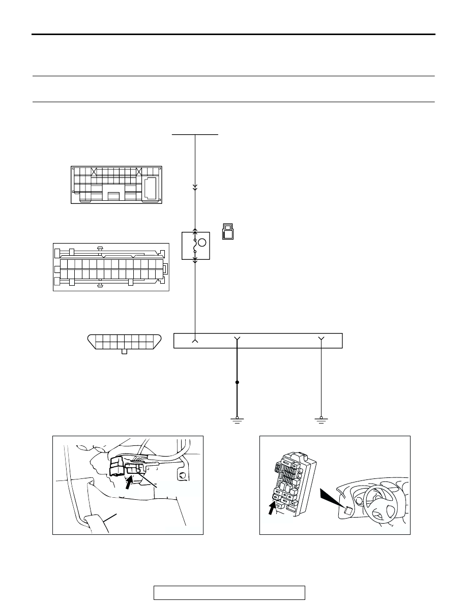
INSPECTION PROCEDURE 1: Communication with Scan Tool Is Not Possible. (Comunication with All 
Systems Is Not Possible.)

AK103261

15

14

13

12

11

10

1 2 3 4 5 6 7 8
9

16

1

15 16

26 27 28 29

32 33 34

17 18 19 20 21 22 23 24 25

30 31

36 37

35

38

10

11 12 13

1 2 3

4 5 6 7 8 9

14

RED

RED

RED-BLA

C

K

BLA

C

K

BLA

C

K

BLA

C

K

FUSIBLE LINK (1)

Data Link Connector Circuit

C-89

C-113

C-29

DATA LINK
CONNECTOR

38

1

12

16

4

5

JUNCTION
BLOCK

1

6

4 5

11

10

1213

15

17

16

14

19

18

8 9

7

20

2 3

2122 23 2425 26 27 28

C-108

10

15A

AK300113

CONNECTOR: C-29

ACCELERATOR
PEDAL

DATA  LINK
CONNECTOR

AB

C-29 (B)

AK300126

CONNECTOR: C-113

AB

C-113 (B)

MULTIPORT FUEL INJECTION (MFI) DIAGNOSIS

TSB Revision

MULTIPORT FUEL INJECTION (MFI) <2.4L>

13A-738

.

CIRCUIT OPERATION

• A battery positive voltage is applied on the data 

link connector power terminal (terminal No. 16). 
The ground terminals (terminal No. 4, No. 5) are 
grounded to the vehicle body.

.

COMMENT

• The cause is probably a defect in power supply 

system (including ground) for the on-board diag-
nostic test mode line.

.

TROUBLESHOOTING HINTS (The most likely 
causes for this case: ) 

• Malfunction of the data link connector.

• Damaged harness wire.

DIAGNOSIS

STEP 1. Measure the power supply voltage at data link 
connector C-29.
(1) Measure voltage between terminal No. 16 and ground.

• Voltage should be battery positive voltage.

Q: Is battery positive voltage (approximately 12 volts) 

present?
YES : 
Go to step 2. 
NO :  Check harness connectors C-108, C-113 and C-89 at 

intermediate connector for damage, and repair or 
replace as required. Refer to GROUP 00E, Harness 
Connector Inspection 

P.00E-2

. If intermediate 

connectors are in good condition, repair harness wire 
between fusible link (1) and data link connector C-29 
(terminal No. 16) because of open circuit. Then 
confirm that the malfunction symptom is eliminated.

AK300123

CONNECTOR: C-108

AB

C-108

AK300118

CONNECTOR: C-89

AC

C-89

AK300450

1 2 3 4 5 6

12

11

10

1516

14

13

9

7 8

CONNECTOR: C-29

AB

C-29 (B)

HARNESS CONNECTOR:
COMPONENT SIDE

AKX01430AS

1 2 3 4 5 6 7 8
9 10 111213141516

C-29 HARNESS 
CONNECTOR: 
COMPONENT SIDE

MULTIPORT FUEL INJECTION (MFI) DIAGNOSIS

TSB Revision

MULTIPORT FUEL INJECTION (MFI) <2.4L>

13A-739

STEP 2. Check the continuity at data link connector C-29.
(1) Check for the continuity between terminal No. 4, No. 5 and 

ground.

• Should be less than 2 ohms.

Q: Is the continuity normal?

YES :  Replace the scan tool. Then confirm that the 

malfunction symptom is eliminated.

NO :  Repair harness wire between data link connector 

C-29 (terminal No. 4, No. 5) and ground because of 
open circuit or harness damage. Then confirm that 
the malfunction symptom is eliminated.

AK300450

1 2 3 4 5 6

12

11

10

1516

14

13

9

7 8

CONNECTOR: C-29

AB

C-29 (B)

HARNESS CONNECTOR:
COMPONENT SIDE

AKX01431AP

1 2 3 4 5 6 7 8
9 10 111213141516

C-29 HARNESS 
CONNECTOR: 
COMPONENT SIDE

MULTIPORT FUEL INJECTION (MFI) DIAGNOSIS

TSB Revision

MULTIPORT FUEL INJECTION (MFI) <2.4L>

13A-740

INSPECTION PROCEDURE 2: Communication with Scan Tool Is Not Possible (Communication with 
ECM or PCM Only Is Not Possible)

AK101524

58

60 61

53

52

51

55

54

56

59

62

57

RED-

WHITE

RED-

WHITE

RED-

WHITE

ENGINE CONTROL
MODULE (ECM) <M/T>
OR
POWERTRAIN CONTROL
MODULE (PCM) <A/T>

JOINT
CONNECTOR (1)

DATA LINK
CONNECTOR

C-57 <A/T>
(MU803782)

C-56 <M/T>
(MU803770)

C-28

C-77

C-29

62 <M/T>
85 <A/T>

9

12

15

7

98

78

71

88 89

76 77

72
79
91

73
80

74

75

81
92

8283
93

8485

94

8687

9596

90

97

7 8

5

3 4

35

34

10 11 12

2122 23 24

13 14 15

25 26 27

16

28

17

18 19 20

29

30 31

32 33

36 37

38

9

1 2

6

16

15

18

17

14

20

22

21

9

7

1 2

5

19

3

33

32

30 31

29

28

25

24

23

27

26

6

11

13

4

10

8

12

15

14

13

12

11

10

1 2 3 4 5 6 7 8
9

16

Data Link Connector Circuit

AK300113

CONNECTOR: C-29

ACCELERATOR
PEDAL

DATA  LINK
CONNECTOR

AB

C-29 (B)

AK300060

ECM

CONNECTOR: C-56 <M/T>

AF

C-56 (G)


Content   ..  309  310  311  312   ..