Mitsubishi Eclipse. Manual - part 308
MULTIPORT FUEL INJECTION (MFI) DIAGNOSIS
TSB Revision
MULTIPORT FUEL INJECTION (MFI) <2.4L>
13A-725
STEP 18. Test the OBD-II drive cycle.
(1) Carry out a test drive with the drive cycle pattern. Refer to
Diagnostic Function
− OBD-II Drive Cycle − Procedure 6 −
Other Monitor
(2) Check the diagnostic trouble code (DTC).
Q: Is DTC P2228 set?
YES : Retry the troubleshooting.
NO : The inspection is complete.
DTC P2229: Barometric Pressure Circuit High Input
AK300332
7
4 5 6
1 2 3
GREEN-
YELL
OW
GREEN-
WHITE
BROWN
C-54 <A/T>
(MU803781)
C-60 <M/T>
(MU803772)
ENGINE CONTROL
MODULE (ECM) <M/T>
OR
POWERTRAIN CONTROL
MODULE (PCM) <A/T>
81 <M/T>*1
46 <A/T>*3
5 V
85 <M/T>*1
55 <A/T>*3
40 <M/T>*2
16 <A/T>*4
B-14
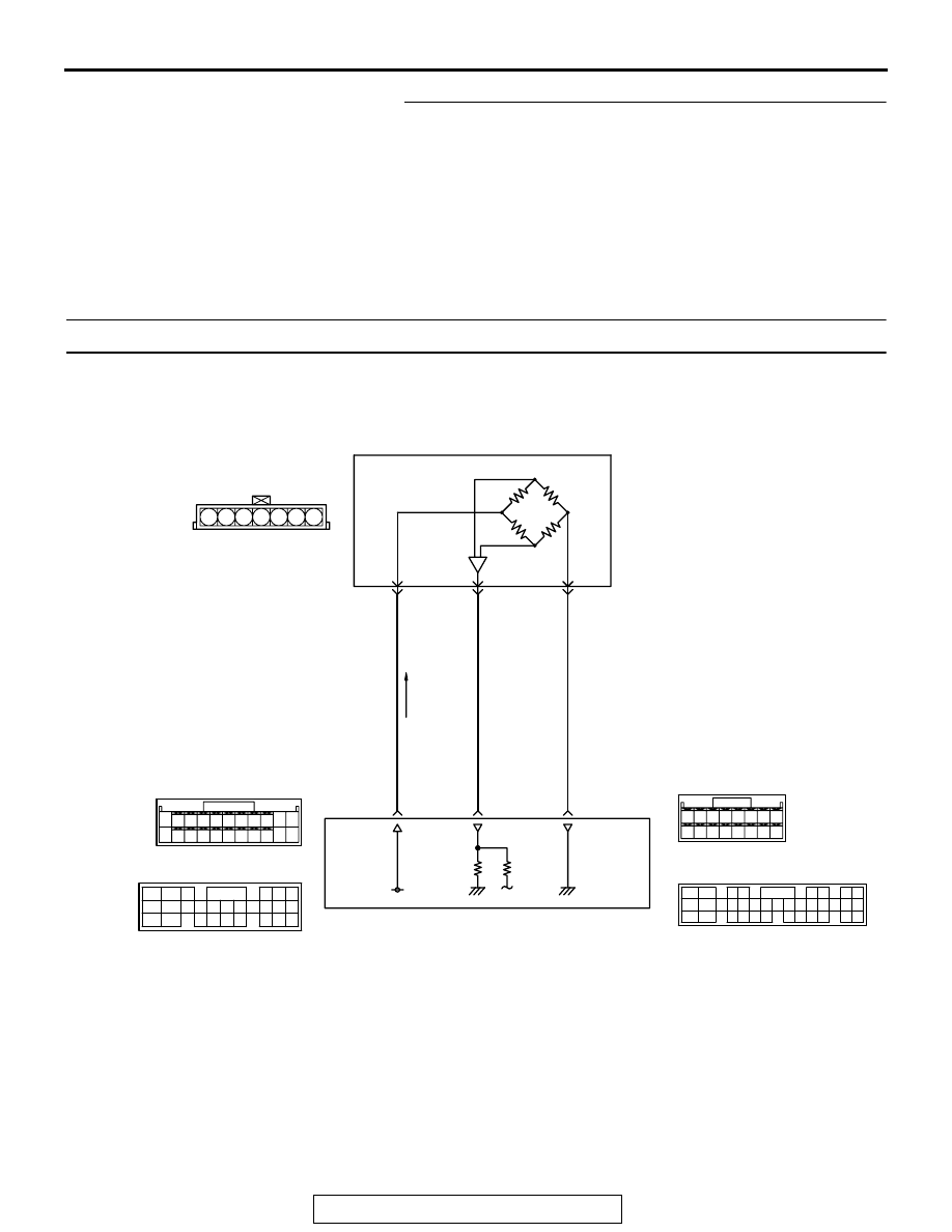
BAROMETRIC PRESSURE SENSOR
(INCORPORATED IN VOLUME
AIRFLOW SENSOR)
1
2
5
82
78
81
80
89 90 91 92
79
87
71
74
73
72
76
75
77
85
88
83 84
86
42 43
48 49 50 51 52 53 54 55 56 57
46
45
44
58 59
60 61 62 63
64 65 66
47
41
Barometric Pressure Sensor Circuit
2
3 4
5 6
7 8
9
11 12 13 14 15 16 17 18 19 20
30
21 22 23
24 25
26 27 28 29
3132 33
34 35
1
10
C-50 <A/T>
(MU803784)
NOTE
*1: ECM connector C-60 <M/T>
*2: ECM connector C-53 <M/T>
*3: PCM connector C-54 <A/T>
*4: PCM connector C-50 <A/T>
C-53 <M/T>
(MU803771)
34
33
32
36
35
37
42
45
31
39
38
46
40 41
43 44