Mitsubishi Eclipse. Manual - part 229


  Index      Mitsubishi     Mitsubishi Eclipse - service repair manual 2004 year


Search            


Content   ..  227  228  229  230   ..


Mitsubishi Eclipse. Manual - part 229


MULTIPORT FUEL INJECTION (MFI) DIAGNOSIS

TSB Revision

MULTIPORT FUEL INJECTION (MFI) <2.4L>

13A-409

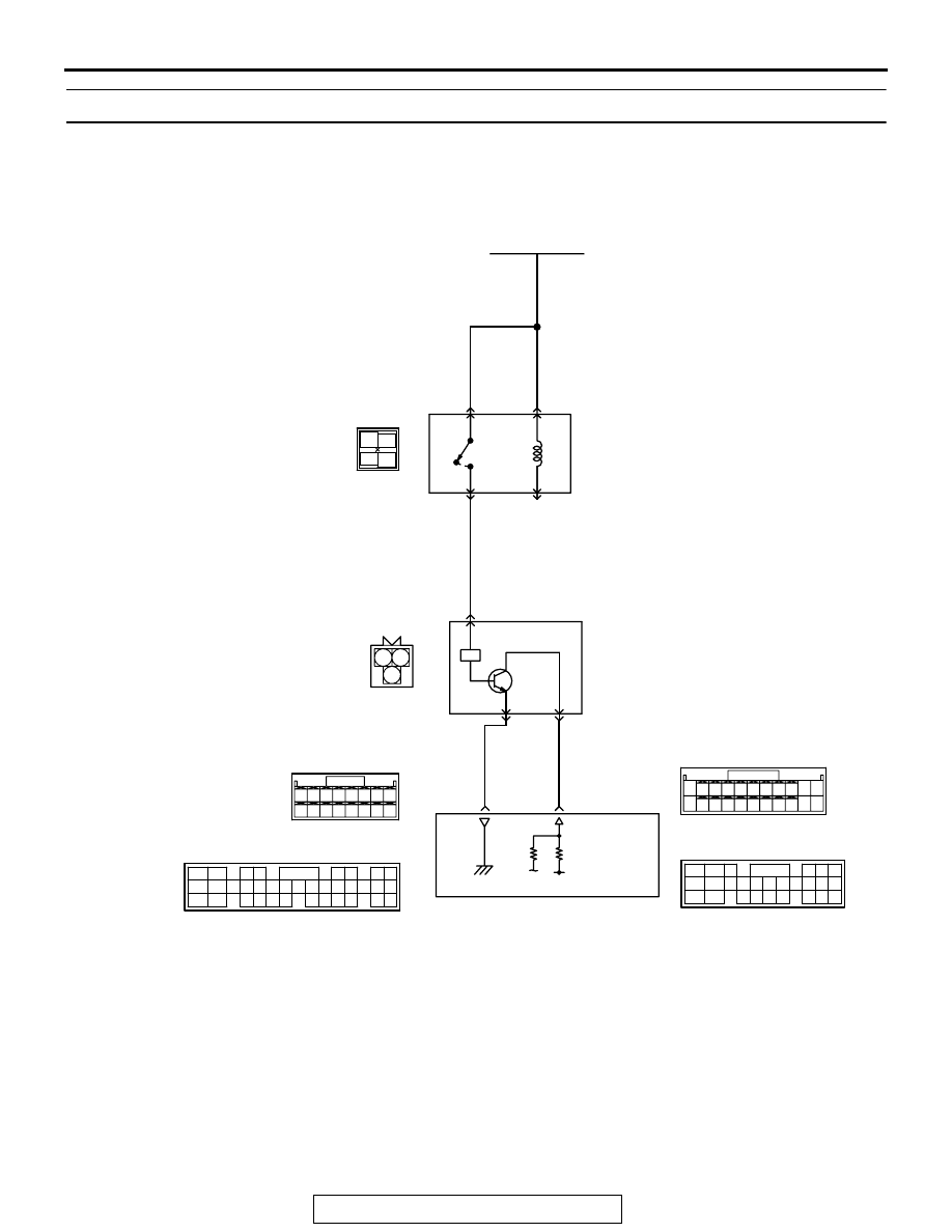
DTC P0335: Crankshaft Position Sensor Circuit

AK101516

1 2

3

RED

-

WHITE

RED

-

WHITE

RED

-

WHITE

RED

BROWN

GREEN-

RED

BATTERY

MFI
RELAY

CRANKSHAFT
POSITION
SENSOR

     B-20
MU802603

C-54 <A/T>
(MU803781)

C-60 <M/T>
(MU803772)

89 <M/T>

*2

45 <A/T>

*4

40 <M/T>

*1

16 <A/T>

*3

4

1

2

3

3

1

2

5 V

ENGINE CONTROL
MODULE (ECM) <M/T>
OR
POWERTRAIN CONTROL
MODULE (PCM) <A/T>

42 43
48 49 50 51 52 53 54 55 56 57

46

45

44

58 59

60 61 62 63

64 65 66

47

41

82

78

81

80

89 90 91 92

79

87

71

74

73

72

76

75

77

85

88

83 84

86

Crankshaft Position Sensor Circuit

2

3 4

5 6

7 8

9

11 12 13 14 15 16 17 18 19 20

30

21 22 23

24 25

26 27 28 29

3132 33

34 35

1

10

C-50 <A/T>
(MU803784)

NOTE
*1: ECM connector C-53 <M/T>
*2: ECM connector C-60 <M/T>
*3: PCM connector C-50 <M/T>
*4: PCM connector C-54 <A/T>

C-53 <M/T>
(MU803771)

34

33

32

36

35

37

42

45

31

39

38

46

40 41

43 44

3 4

1 2

A-18X

MULTIPORT FUEL INJECTION (MFI) DIAGNOSIS

TSB Revision

MULTIPORT FUEL INJECTION (MFI) <2.4L>

13A-410

.

CIRCUIT OPERATION

• The crankshaft position sensor power is supplied 

from the MFI relay (terminal No. 4).

• Terminal No. 1 of the crankshaft position sensor 

is grounded with ECM (terminal No. 40) <M/T> or 
PCM (terminal No. 16) <A/T>.

• A 5-volt voltage is applied on the crankshaft posi-

tion sensor output terminal (terminal No. 2) from 
the ECM (terminal No. 89) <M/T> or PCM (termi-
nal No. 45) <A/T>. The crankshaft position sen-
sor generates a pulse signal when the output 
terminal is opened and grounded.

.

TECHNICAL DESCRIPTION

• The crankshaft position sensor detects the crank 

angle (position) of each cylinder, and converts 
that data to pulse signals, which are then input to 
the ECM <M/T> or PCM <A/T>.

• When the engine is running, the crankshaft posi-

tion sensor outputs a pulse signal.

• The ECM <M/T> or PCM <A/T> checks whether 

pulse signal is input while the engine is cranking.

.

DESCRIPTIONS OF MONITOR METHODS

• Crankshaft position sensor signal does not 

change.

• Crankshaft position sensor signal is not normal 

pattern.

.

MONITOR EXECUTION
Continuous

.

MONITOR EXECUTION CONDITIONS (Other 
monitor and Sensor)

Other Monitor (There is no temporary DTC stored 

in memory for the item monitored below)

• Not applicable

Sensor (The sensor below is determined to be 

normal)

• Not applicable

.

AK300060

ECM

CONNECTORS: C-53, C-60 <M/T>

AN

C-53 (G)

C-60 (G)

AK300060

PCM

CONNECTORS: C-50, C-54 <A/T>

AO

C-54 (GR)

C-50 (GR)

AK300071AB

B-20 (B)

CRANKSHAFT
POSITION
SENSOR

CONNECTOR: B-20

AK300121

MFI RELAY

CONNECTOR: A-18X

AB

A-18X

MULTIPORT FUEL INJECTION (MFI) DIAGNOSIS

TSB Revision

MULTIPORT FUEL INJECTION (MFI) <2.4L>

13A-411

DTC SET CONDITIONS<Range/Performance problem-aligment>

Logic Flow Chart

.

Check Conditions

• Engine is being cranked.

Judgment Criteria

• Crankshaft position sensor output voltage has not 

changed (no pulse signal is input) for 2 seconds.

.

START

END

YES

NO

NO

YES

MALFUNCTION

GOOD

CONTINUOUS

FAILURE FOR 2secs

EXPECTED STATE

OF THE SENSOR

MONITORING 
CONDITIONS?

YES

NO

AK301446

MULTIPORT FUEL INJECTION (MFI) DIAGNOSIS

TSB Revision

MULTIPORT FUEL INJECTION (MFI) <2.4L>

13A-412

DTC SET CONDITIONS<Circuit Continuity>

Logic Flow Chart

.

Check Conditions, Judgment Criteria

• Normal signal pattern has not been input for cyl-

inder identification from the crankshaft position 
sensor signal and camshaft position sensor sig-
nal for 2 seconds.

.

OBD-ll DRIVE CYCLE PATTERN
Refer to Diagnostic Function 

− OBD-ll Drive Cycle − 

Procedure 6 

− Other Monitor 

P.13A-5

.

.

TROUBLESHOOTING HINTS (The most likely 
causes for this code to be set are:)

• Crankshaft position sensor failed.

• Crankshaft sensing blade failed.

• Open or shorted crankshaft position sensor cir-

cuit, or connector damage.

• ECM failed. <M/T>

• PCM failed. <A/T>

DIAGNOSIS

Required Special Tools:

• MB991958 (MUT-III Sub Assembly)

• MB991824: V.C.I.

• MB991827: USB Cable

• MB991911: Main Harness B

• MD998478: Test Harness (3pin, triangle)

START

MONITORING
CONDITIONS

END

NO

NO

NO

YES

YES

YES

MALFUNCTION

GOOD

OUTPUT SIGNAL

CHANGES

CONTINUOUS

FAILURE FOR 2secs

AK301487


Content   ..  227  228  229  230   ..