Mitsubishi Eclipse. Manual - part 193
MULTIPORT FUEL INJECTION (MFI) DIAGNOSIS
TSB Revision
MULTIPORT FUEL INJECTION (MFI) <2.4L>
13A-265
DTC SET CONDITIONS
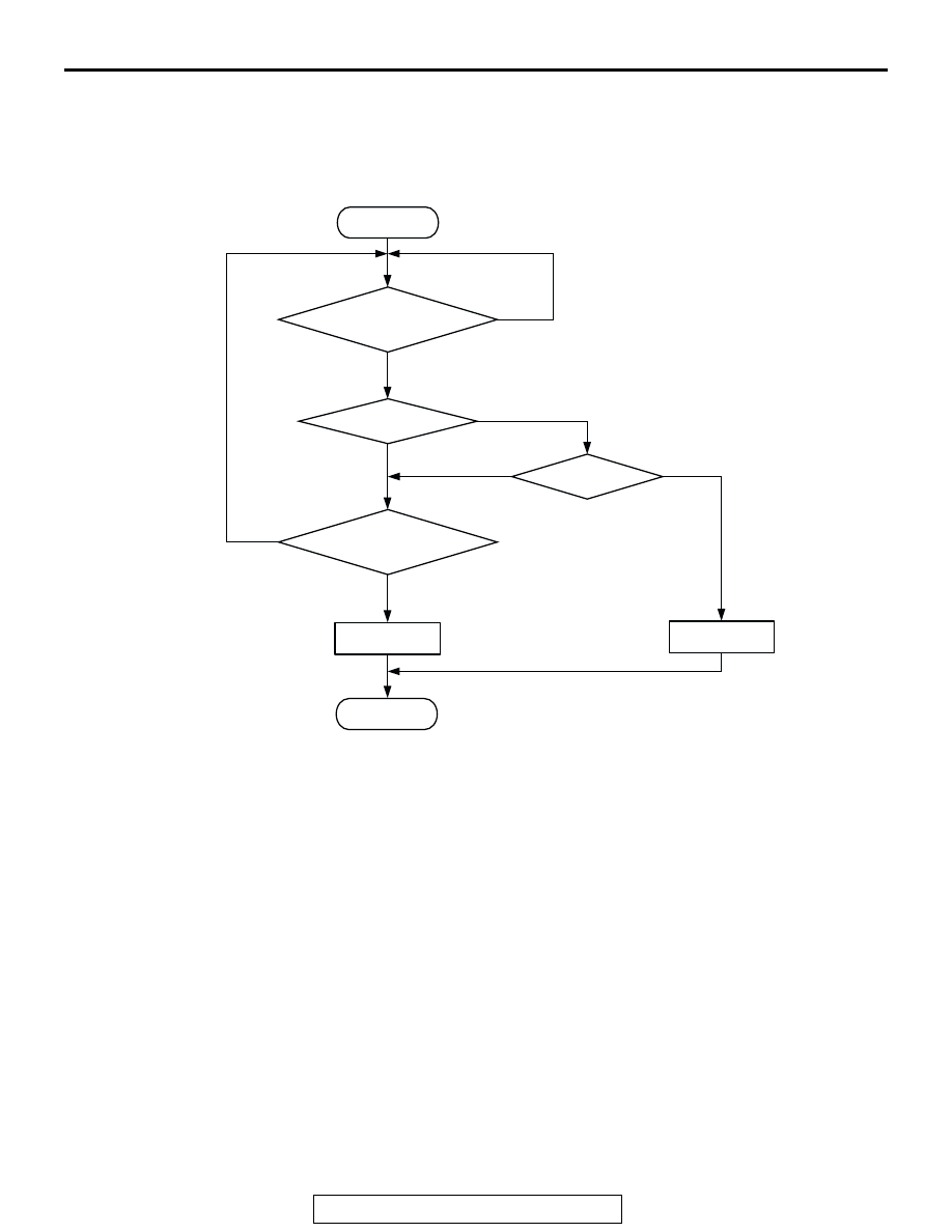
Logic Flow Chart
.
Check Conditions
• 60 seconds have elapsed from the start of the
previous monitoring.
• Engine coolant temperature is higher than 20°C
(68
°F).
• While the heated oxygen sensor (front) heater is
on.
• Battery positive voltage is at between 11 and 16.5
volts.
Judgment Criteria
• Heater current of the heated oxygen sensor
(front) heater has continued to be lower than 0.16
ampere or higher than 7.5 ampere for 4 seconds.
.
OBD-ll DRIVE CYCLE PATTERN
Refer to Diagnostic Function
− OBD-ll Drive Cycle −
Procedure 6
.
.
TROUBLESHOOTING HINTS (The most likely
causes for this code to be set are: )
• Open or shorted heated oxygen sensor (front)
heater circuit, harness damage, or connector
damage.
• Open circuit in heated oxygen sensor (front)
heater.
• ECM failed. <M/T>
• PCM failed. <A/T>
DIAGNOSIS
Required Special Tool:
• MD998464: Test Harness
START
END
YES
YES
YES
YES
NO
NO
NO
NO
MALFUNCTION
GOOD
CONTINUOUS
FAILURE FOR 4secs
MONITORING
CONDITIONS
CURRENT < 0.16A
CURRENT > 7.5A
AK301439