Mitsubishi Eclipse. Manual - part 189
MULTIPORT FUEL INJECTION (MFI) DIAGNOSIS
TSB Revision
MULTIPORT FUEL INJECTION (MFI) <2.4L>
13A-249
DTC SET CONDITIONS
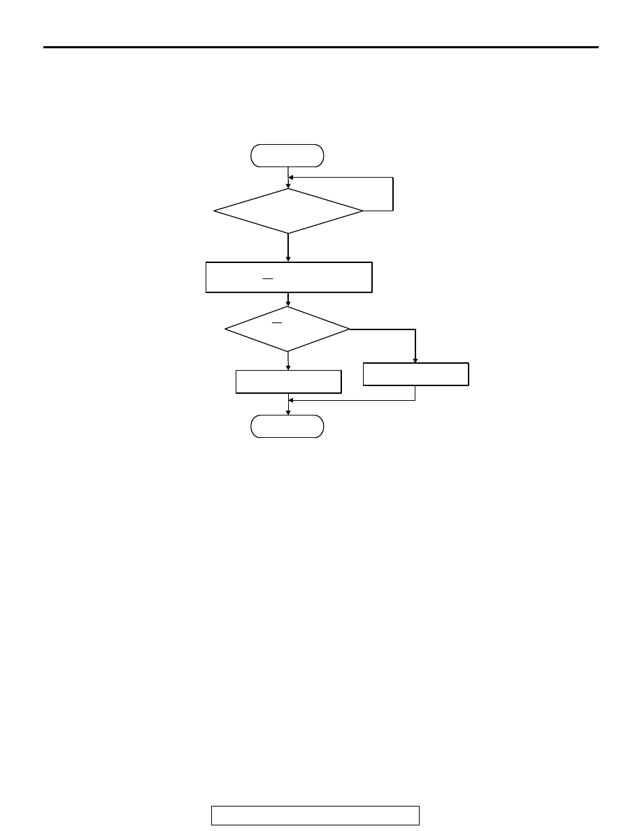
Logic Flow Chart
.
Check Conditions
• Engine coolant temperature is higher than 60°C
(140
°F).
• Engine speed is at between 1,500 and 3,000
r/min <M/T> or 1,200 and 3,000 r/min <A/T>.
• Volumetric efficiency is at between 21 and 60
<M/T> or 30 and 60 <A/T> percent.
• Under the closed loop air/fuel control.
• The throttle valve is open.
• Short-term fuel trim is higher than −25 and lower
than +25 percent.
• More than 2 seconds have elapsed after the
above mentioned conditions have been met.
• The ECM<M/T> or PCM<A/T> monitors for this
condition for 7 cycles of 10 second each during
the drive cycle.
Judgment Criteria
• The heated oxygen sensor (front) sends "lean"
and "rich" signals alternately 8 times or less for
10 seconds.
NOTE: If the sensor switching frequency is lower
than the Judgment Criteria due to the MB991958
OBD-II test Mode
−
H02S Test Results, it is assumed
that the heated oxygen sensor has deteriorated. If it
is higher, it is assumed that the harness is damaged
or has a short circuit.
If the heated oxygen sensor signal voltage has not
changed even once (lean/rich) after the DTC was
erased, the sensor switch time will display as 0 sec-
onds.
.
OBD-ll DRIVE CYCLE PATTERN
Refer to Diagnostic Function
− OBD-ll Drive Cycle −
Procedure 4
− Heated Oxygen Sensor Monitor
.
TROUBLESHOOTING HINTS (The most likely
causes for this code to be set are: )
• Heated oxygen sensor (front) deteriorated.
F1: THRESHOLD VALUE FOR REAL-TIME SWITDHING FREQUENCY
F0: THRESHOLD VALUE FOR AVERAGE SWITDHING FREQUENCY
START
MONITORING
CONDITIONS
MALFUNCTION
GOOD
END
NO
NO
YES
YES
Ff < F0
CALCULATE AVERAGE SWITCHING
FREQUENCY (Ff) OVER SPECIFIED TIMES
AK301438