Mitsubishi Eclipse. Manual - part 186


  Index      Mitsubishi     Mitsubishi Eclipse - service repair manual 2004 year


Search            


Content   ..  184  185  186  187   ..


Mitsubishi Eclipse. Manual - part 186


MULTIPORT FUEL INJECTION (MFI) DIAGNOSIS

TSB Revision

MULTIPORT FUEL INJECTION (MFI) <2.4L>

13A-237

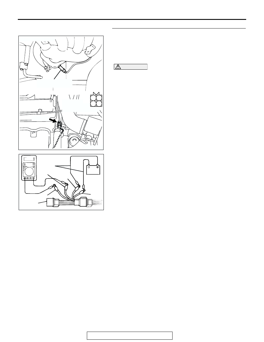
STEP 2. Check the heated oxygen sensor (front).
(1) Disconnect the heated oxygen sensor (front) connector 

B-17 and connect test harness special tool, MD998464, to 
the connector on the heated oxygen sensor (front) side.

(2) Warm-up the engine until engine coolant 80

°C (176°F) or 

higher.

CAUTION

Be very careful when connecting the jumper wires; incor-
rect connection can damage the heated oxygen sensor 
(front).

(3) Use the jumper wires to connect terminal No. 1 (red clip) to 

the positive battery terminal and terminal No. 3 (blue clip) to 
the negative battery terminal.

(4) Connect a digital volt meter between terminal No. 2 (black 

clip) and terminal No. 4 (white clip).

(5) While repeatedly revving the engine, measure the heated 

oxygen sensor (front) output voltage.

Standard value: 0.6 

 1.0 volt

Q: Is the voltage between 0.6 and 1.0 volt?

YES : Go to Step 3.
NO :  Replace the heated oxygen sensor (front). Then go to 

Step 5.

AK300403

1

2

3

4

AB

B-17 (B)

HEATED OXYGEN
SENSOR (FRONT)

CONNECTOR: B-17

HARNESS 
CONNECTOR:
COMPONENT SIDE

AKX01625AC

BLUE

RED

BLACK

JUMPER
WIRES

WHITE

MD998464

MULTIPORT FUEL INJECTION (MFI) DIAGNOSIS

TSB Revision

MULTIPORT FUEL INJECTION (MFI) <2.4L>

13A-238

STEP 3. Check connector B-17 at heated oxygen sensor 
(front) and connector C-60 at ECM <M/T> or connector 
C-57 at PCM <A/T> for damage.
Q: Is the connector in good condition?

YES : Go to Step 4.
NO :  Repair or replace it. Refer to GROUP 00E, Harness 

Connector Inspection 

P.00E-2

. Then go to Step 5.

AK300403

1

2

3

4

AB

B-17 (B)

HEATED OXYGEN
SENSOR (FRONT)

CONNECTOR: B-17

HARNESS 
CONNECTOR:
COMPONENT SIDE

AK300415

82

78

8180

89

90

91

92

79

87

71

74 73 72

76 75

77

85

88

83

84

86

CONNECTOR: C-60 <M/T>

AB

C-60 (G)

HARNESS CONNECTOR:
COMPONENT SIDE

MULTIPORT FUEL INJECTION (MFI) DIAGNOSIS

TSB Revision

MULTIPORT FUEL INJECTION (MFI) <2.4L>

13A-239

STEP 4. Check for short circuit to ground between heated 
oxygen sensor (front) connector B-17 (terminal No. 4) and 
ECM connector C-60 (terminal No. 76) <M/T> or PCM 
connector C-57 (terminal No. 71) <A/T>.
Q: Is the harness wire in good condition?

YES : Replace the ECM or PCM. Then go to Step 5.
NO :  Repair it. Then go to Step 5.

AK300735

98

78

71

88

89

76

77

72
79
91

73
80

74

75

81
92

82

83

93

84

85

94

86

87

95

96

90

97

CONNECTOR: C-57 <A/T>

C-57 (GR)

AB

HARNESS CONNECTOR:
COMPONENT SIDE

AK300403

1

2

3

4

AB

B-17 (B)

HEATED OXYGEN
SENSOR (FRONT)

CONNECTOR: B-17

HARNESS 
CONNECTOR:
COMPONENT SIDE

MULTIPORT FUEL INJECTION (MFI) DIAGNOSIS

TSB Revision

MULTIPORT FUEL INJECTION (MFI) <2.4L>

13A-240

STEP 5. Test the OBD-II drive cycle.
(1) Carry out a test drive with the drive cycle pattern. Refer to 

Diagnostic Function 

− OBD-II Drive Cycle − Procedure 6 − 

Other Monitor 

P.13A-5

.

(2) Check the diagnostic trouble code (DTC).
Q: Is DTC P0131 set?

YES : Retry the troubleshooting.
NO :  The inspection is complete.

AK300415

82

78

8180

89

90

91

92

79

87

71

74 73 72

76 75

77

85

88

83

84

86

CONNECTOR: C-60 <M/T>

AB

C-60 (G)

HARNESS CONNECTOR:
COMPONENT SIDE

AK300735

98

78

71

88

89

76

77

72
79
91

73
80

74

75

81
92

82

83

93

84

85

94

86

87

95

96

90

97

CONNECTOR: C-57 <A/T>

C-57 (GR)

AB

HARNESS CONNECTOR:
COMPONENT SIDE


Content   ..  184  185  186  187   ..