Mitsubishi Eclipse. Manual - part 172


  Index      Mitsubishi     Mitsubishi Eclipse - service repair manual 2004 year


Search            


Content   ..  170  171  172  173   ..


Mitsubishi Eclipse. Manual - part 172


MULTIPORT FUEL INJECTION (MFI) DIAGNOSIS

TSB Revision

MULTIPORT FUEL INJECTION (MFI) <2.4L>

13A-181

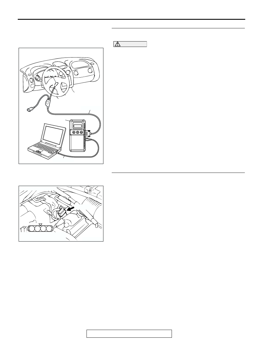
STEP 1. Using scan tool MB991958, check data list item 14: 
Throttle Position Sensor.

CAUTION

To prevent damage to scan tool MB991958, always turn the 
ignition switch to the "LOCK" (OFF) position before con-
necting or disconnecting scan tool MB991958.
(1) Connect scan tool MB991958 to the data link connector.
(2) Turn the ignition switch to the "ON" position.
(3) Set scan tool MB991958 to the data reading mode for item 

14, Throttle Position Sensor.

• With the throttle valve in the idle position, voltage should 

be between 0.535 and 0.735 volt.

• With the throttle valve in the full-open position, voltage 

should be between 4.5 and 5.5 volts.

(4) Turn the ignition switch to the "LOCK" (OFF) position.
Q: Is the sensor operating properly?

YES : It can be assumed that this malfunction is intermittent. 

Refer to GROUP 00, How to Use 
Troubleshooting/Inspection Service Points 

P.00-6

.

NO :  Go to Step 2.

STEP 2. Check connector B-07 at throttle position sensor 
for damage.
Q: Is the connector in good condition?

YES : Go to Step 3.
NO :  Repair or replace it. Refer to GROUP 00E, Harness 

Connector Inspection 

P.00E-2

. Then go to Step 11.

AK300810

AB

MB991911

16-PIN

MB991827

MB991824 

AK300402

2 1

3

4

CONNECTOR: B-07

AB

B-07 (B)

HARNESS CONNECTOR:
COMPONENT SIDE

MULTIPORT FUEL INJECTION (MFI) DIAGNOSIS

TSB Revision

MULTIPORT FUEL INJECTION (MFI) <2.4L>

13A-182

STEP 3. Measure the sensor supply voltage at throttle 
position sensor harness side connector B-07.
(1) Disconnect the connector B-07 and measure at the harness 

side.

(2) Turn the ignition switch to the "ON" position.

(3) Measure the voltage between terminal No. 4 and ground.

• Voltage should be between 4.8 and 5.2 volts.

(4) Turn the ignition switch to the "LOCK" (OFF) position.
Q: Is the measured voltage between 4.8 and 5.2 volts?

YES : Go to Step 6.
NO :  Go to Step 4.

AK300402

2 1

3

4

CONNECTOR: B-07

AB

B-07 (B)

HARNESS CONNECTOR:
COMPONENT SIDE

AK000236 AJ

B-07 HARNESS 
CONNECTOR: 
COMPONENT SIDE

4 3 2 1

MULTIPORT FUEL INJECTION (MFI) DIAGNOSIS

TSB Revision

MULTIPORT FUEL INJECTION (MFI) <2.4L>

13A-183

STEP 4. Check connector C-60 at ECM <M/T> or connector 
C-54 at PCM <A/T> for damage.
Q: Is the connector in good condition?

YES : Go to Step 5.
NO :  Repair or replace it. Refer to GROUP 00E, Harness 

Connector Inspection 

P.00E-2

. Then go to Step 11.

AK300415

82

78

8180

89

90

91

92

79

87

71

74 73 72

76 75

77

85

88

83

84

86

CONNECTOR: C-60 <M/T>

AB

C-60 (G)

HARNESS CONNECTOR:
COMPONENT SIDE

AK300412

42

43

48

49

50

51

52

53

54

55

56

57

46 45 44

58

59

60

61

62

63

64

65

66

47

41

C-54 (GR)

CONNECTOR: C-54 <A/T>

AB

HARNESS CONNECTOR:
COMPONENT SIDE

MULTIPORT FUEL INJECTION (MFI) DIAGNOSIS

TSB Revision

MULTIPORT FUEL INJECTION (MFI) <2.4L>

13A-184

STEP 5. Check for open circuit and short circuit to ground 
between throttle position sensor connector B-07 (terminal 
No. 3) and ECM connector C-60 (terminal No. 81) <M/T> or 
PCM connector C-54 (terminal No. 46) <A/T>.
Q: Is the harness wire in good condition?

YES : Replace the ECM or PCM. Then go to Step 11.
NO :  Repair it. Then go to Step 11.

AK300402

2 1

3

4

CONNECTOR: B-07

AB

B-07 (B)

HARNESS CONNECTOR:
COMPONENT SIDE

AK300415

82

78

8180

89

90

91

92

79

87

71

74 73 72

76 75

77

85

88

83

84

86

CONNECTOR: C-60 <M/T>

AB

C-60 (G)

HARNESS CONNECTOR:
COMPONENT SIDE

AK300412

42

43

48

49

50

51

52

53

54

55

56

57

46 45 44

58

59

60

61

62

63

64

65

66

47

41

C-54 (GR)

CONNECTOR: C-54 <A/T>

AB

HARNESS CONNECTOR:
COMPONENT SIDE


Content   ..  170  171  172  173   ..