Mitsubishi Eclipse. Manual - part 159


  Index      Mitsubishi     Mitsubishi Eclipse - service repair manual 2004 year


Search            


Content   ..  157  158  159  160   ..


Mitsubishi Eclipse. Manual - part 159


MULTIPORT FUEL INJECTION (MFI) DIAGNOSIS

TSB Revision

MULTIPORT FUEL INJECTION (MFI) <2.4L>

13A-129

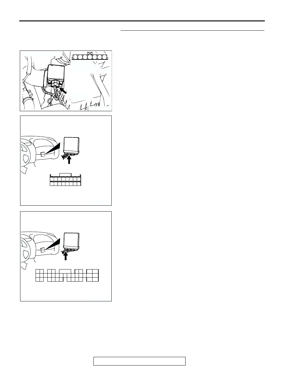
STEP 10. Check for open circuit between intake air 
temperature sensor connector B-14 and ECM connector 
C-53 <M/T> or PCM connector C-50 <A/T>.
Q: Is the harness wire in good condition?

YES : Replace the ECM or PCM. Then go to Step 11.
NO :  Repair it. Then go to Step 11.

AK300078

3

4

5

1

2

6

7

CONNECTOR: B-14

AB

B-14 (B)

HARNESS 
CONNECTOR:
COMPONENT SIDE

AK300417

34 33 32

36 35

37

42

45

31

39

38

46

40

41

43

44

CONNECTOR: C-53 <M/T>

C-53 (G)

AB

HARNESS CONNECTOR:
COMPONENT SIDE

AK300414

2

3

4

5

6

7

8

9

11

12

13

14

15

16

17

18

19

20

30

21

22

23

24

25

26

27

28

29

31

32

33

34

35

1

10

C-50 (GR)

CONNECTOR: C-50 <A/T>

AB

HARNESS CONNECTOR:
COMPONENT SIDE

MULTIPORT FUEL INJECTION (MFI) DIAGNOSIS

TSB Revision

MULTIPORT FUEL INJECTION (MFI) <2.4L>

13A-130

STEP 11. Test the OBD-II drive cycle.
(1) Carry out a test drive with the drive cycle pattern. Refer to 

Diagnostic Function 

− OBD-II Drive Cycle − Procedure 6 − 

Other Monitor 

P.13A-5

.

(2) Check the diagnostic trouble code (DTC).
Q: Is DTC P0113 set?

YES : Retry the troubleshooting.
NO :  The inspection is complete.

DTC P0116: Engine Coolant Temperature Circuit Range/Performance Problem

AK000655

1 2

BL

ACK

YELL

OW

-GREEN

92 <M/T>
57 <A/T>

83 <M/T>
44 <A/T>

C-60 <M/T>
(MU803772)

C-54 <A/T>
(MU803781)

ENGINE CONTROL
MODULE (ECM) <M/T>
OR
POWERTRAIN CONTROL
MODULE (PCM) <A/T>

ENGINE COOLANT
TEMPERATURE SENSOR

        B-11
 (MU802406)

2

1

5V

82

78

81

80

89 90 91 92

79

87

71

74

73

72

76

75

77

85

88

83 84

86

42 43
48 49 50 51 52 53 54 55 56 57

46

45

44

58 59

60 6162 63

64 65 66

47

41

Engine Coolant Temperature Sensor Circuit

AK300052

ENGINE COOLANT
TEMPERATURE
SENSOR

CONNECTOR: B-11

AB

B-11 (B)

AK300060

ECM

CONNECTOR: C-60 <M/T>

AE

C-60 (G)

MULTIPORT FUEL INJECTION (MFI) DIAGNOSIS

TSB Revision

MULTIPORT FUEL INJECTION (MFI) <2.4L>

13A-131

.

CIRCUIT OPERATION

• 5-volt voltage is applied to the engine coolant 

temperature sensor output terminal (terminal No. 
1) from the ECM (terminal No. 83) <M/T> or PCM 
(terminal No. 44) <A/T> via the resistor in the 
ECM <M/T> or PCM <A/T>. The ground terminal 
(terminal No. 2) is grounded with ECM (terminal 
No. 92) <M/T> or (terminal No. 57) <A/T>.

• The engine coolant temperature sensor is a neg-

ative temperature coefficient type of resistor. It 
has the characteristic that when the engine cool-
ant temperature rises the resistor decreases.

• The engine coolant temperature sensor output 

voltage increases when the resistor increases 
and decreases when the resistor decreases.

.

TECHNICAL DESCRIPTION

• The engine coolant temperature sensor converts 

the engine coolant temperature to a voltage and 
output it.

• The ECM <M/T> or PCM <A/T> checks whether 

this voltage is within a specified range.

.

DESCRIPTIONS OF MONITOR METHODS
Engine coolant temperature sensor output voltage 

does not change for specified period when 
engine coolant temperature sensor output volt-
age at engine start is over 7

°C (45°F).

.

MONITOR EXECUTION
Once per driving cycle

.

MONITOR EXECUTION CONDITIONS (Other 
monitor and Sensor)

Other Monitor (There is no temporary DTC stored 

in memory for the item monitored below)

• Not applicable

Sensor (The sensor below is determined to be 

normal)

• Volume airflow sensor

• Engine coolant temperature sensor

• Intake air temperature sensor

.

AK300060AB

C-54 (GR)

PCM

CONNECTOR: C-54 <A/T>

MULTIPORT FUEL INJECTION (MFI) DIAGNOSIS

TSB Revision

MULTIPORT FUEL INJECTION (MFI) <2.4L>

13A-132

DTC SET CONDITIONS

Logic Flow Chart

.

Check Conditions

• Engine coolant temperature was 7°C (45°F) or 

more when the engine started.

Judgement Criteria

• Engine coolant temperature fluctuates within 1°C 

(1.8

°F) after 5 minutes have passed since the 

engine was started.

• However, time is not counted if any of the follow-

ing conditions are met.

1. Intake air temperature is 60

°C (140°F) or 

more.

2. Volume airflow sensor output frequency is 70 

Hz or less.

3. During fuel shut-off operation.

• The ECM<M/T> or PCM<A/T> monitors for this 

condition once during the drive cycle.

.

OBD-ll DRIVE CYCLE PATTERN
Refer to Diagnostic Function

−OBD-ll Drive 

Cycle

−Procedure 6−Other Monitor 

P.13A-5

.

START

END

YES

NO

NO

YES

MALFUNCTION

GOOD

300secs HAVE PASSED?

|dT| < 1˚C(1.8˚F)

MONITORING CONDITIONS?

START MEASURING THE MINIMUM AND MAXIMUM

TEMPERATURE FROM ENGINE START

CALCULATE THE DIFFERENCE OF THE MINIMUM AND 

THE MAXIMUM TEMPERATURE FROM ENGINE START;dT

YES

NO

AK301425


Content   ..  157  158  159  160   ..