Mitsubishi Eclipse. Manual - part 146


  Index      Mitsubishi     Mitsubishi Eclipse - service repair manual 2004 year


Search            


Content   ..  144  145  146  147   ..


Mitsubishi Eclipse. Manual - part 146


MULTIPORT FUEL INJECTION (MFI) DIAGNOSIS

TSB Revision

MULTIPORT FUEL INJECTION (MFI) <2.4L>

13A-77

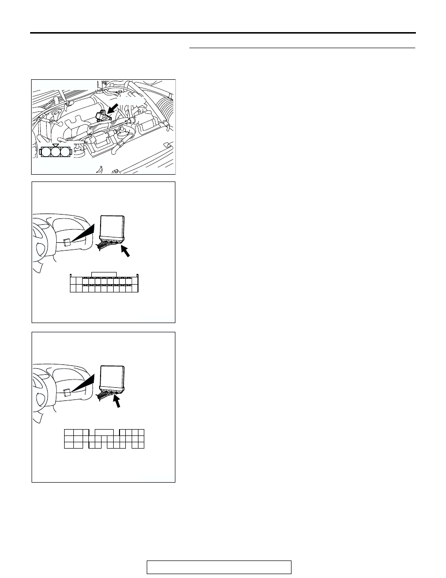
STEP 6. Check connector B-04 at the manifold absolute 
pressure sensor and connector C-60 at ECM <M/T> or 
connector C-57 at PCM <A/T> for damage.
Q: Is the connector in good condition?

YES : Repair harness wire between manifold absolute 

pressure sensor connector B-102 (terminal No. 1) and 
ECM connector C-60 (terminal No. 73) <M/T> or PCM 
connector C-57 (terminal No. 91) <A/T> because of 
open circuit or harness damage. Then go to Step 12.

NO :  Repair or replace it. Refer to GROUP 00E, Harness 

Connector Inspection 

P.00E-2

. Then go to Step 18.

AK300107

1

2

3

AB

CONNECTOR: B-04

B-04 (B)

HARNESS CONNECTOR:
COMPONENT SIDE

AK300415

82

78

8180

89

90

91

92

79

87

71

74 73 72

76 75

77

85

88

83

84

86

CONNECTOR: C-60 <M/T>

AB

C-60 (G)

HARNESS CONNECTOR:
COMPONENT SIDE

AK300735

98

78

71

88

89

76

77

72
79
91

73
80

74

75

81
92

82

83

93

84

85

94

86

87

95

96

90

97

CONNECTOR: C-57 <A/T>

C-57 (GR)

AB

HARNESS CONNECTOR:
COMPONENT SIDE

MULTIPORT FUEL INJECTION (MFI) DIAGNOSIS

TSB Revision

MULTIPORT FUEL INJECTION (MFI) <2.4L>

13A-78

STEP 7. Measure the sensor supply voltage at manifold 
absolute pressure sensor connector B-04 by backprobing.
(1) Do not disconnect the connector B-04.
(2) Turn the ignition switch to the "ON" position.

(3) Measure the voltage between terminal No. 3 and ground by 

backprobing.

• Voltage should be between 4.8 and 5.2 volts.

(4) Turn the ignition switch to the "LOCK" (OFF) position.
Q: Is the measured voltage between 4.8 and 5.2 volts?

YES : Go to Step 12.
NO :  Go to Step 8.

AK300107

1

2

3

AB

CONNECTOR: B-04

B-04 (B)

HARNESS CONNECTOR:
COMPONENT SIDE

3

2

1

AK203036

B-04 HARNESS 
CONNECTOR: 
HARNESS SIDE

AE

MULTIPORT FUEL INJECTION (MFI) DIAGNOSIS

TSB Revision

MULTIPORT FUEL INJECTION (MFI) <2.4L>

13A-79

STEP 8. Measure the sensor supply voltage at ECM 
connector C-60 <M/T> or PCM connector C-54 <A/T> by 
backprobing.
(1) Do not disconnect the connector C-60 <M/T> or connector 

C-54 <A/T>.

(2) Turn the ignition switch to the "ON" position.

AK300415

82

78

8180

89

90

91

92

79

87

71

74 73 72

76 75

77

85

88

83

84

86

CONNECTOR: C-60 <M/T>

AB

C-60 (G)

HARNESS CONNECTOR:
COMPONENT SIDE

AK300412

42

43

48

49

50

51

52

53

54

55

56

57

46 45 44

58

59

60

61

62

63

64

65

66

47

41

C-54 (GR)

CONNECTOR: C-54 <A/T>

AB

HARNESS CONNECTOR:
COMPONENT SIDE

MULTIPORT FUEL INJECTION (MFI) DIAGNOSIS

TSB Revision

MULTIPORT FUEL INJECTION (MFI) <2.4L>

13A-80

(3) Measure the voltage between terminal No. 81 <M/T> or 

terminal No. 46 <A/T> and ground.

• Voltage should be between 4.8 and 5.2 volts.

(4) Turn the ignition switch to the "LOCK" (OFF) position.
Q: Is the measured voltage between 4.8 and 5.2 volts?

YES : Go to Step 9.
NO :  Go to Step 10.

AK000283

7172 73 74 75 76 77 78 79 80 81

82 83 84 85 86 87 88 89 90

92

91

AI

<M/T>

C-60 HARNESS 
CONNECTOR: 
HARNESS SIDE

AK000284 AK

<A/T>

C-54 HARNESS 
CONNECTOR: 
HARNESS SIDE

41 42 43

44 45 46

47 48 49 50 51 52 53 54 55 56 57
58 59

60 61 62 63

64 65 66


Content   ..  144  145  146  147   ..