Mitsubishi Eclipse. Manual - part 137
MULTIPORT FUEL INJECTION (MFI) DIAGNOSIS
TSB Revision
MULTIPORT FUEL INJECTION (MFI) <2.4L>
13A-41
STEP 8. Replace the volume airflow sensor.
(1) Replace the volume airflow sensor.
(2) Carry out a test drive with the drive cycle pattern. Refer to
Diagnostic Function
− OBD-II Drive Cycle − Procedure 6 −
Other Monitor
(3) Check the diagnostic trouble code (DTC).
Q: Is DTC P0101 set?
YES : Replace the ECM or PCM. Then go to Step 9.
NO : The inspection is complete.
STEP 9. Test the OBD-II drive cycle.
(1) Carry out a test drive with the drive cycle pattern. Refer to
Diagnostic Function
− OBD-II Drive Cycle − Procedure 6 −
Other Monitor
(2) Check the diagnostic trouble code (DTC).
Q: Is DTC P0101 set?
YES : Retry the troubleshooting.
NO : The inspection is complete.
AK300078
3
4
5
1
2
6
7
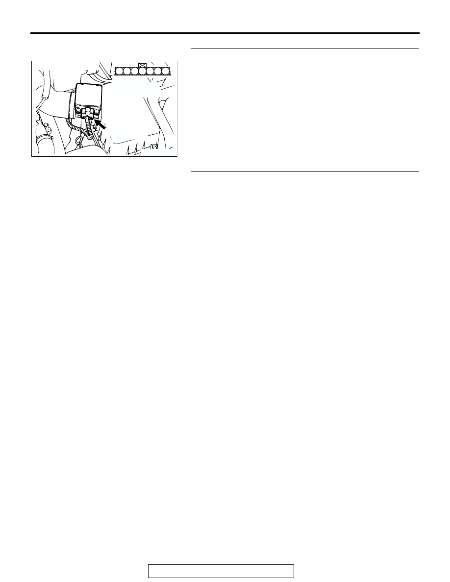
CONNECTOR: B-14
AB
B-14 (B)
HARNESS
CONNECTOR:
COMPONENT SIDE