Mitsubishi Eclipse. Manual - part 123
TIMING BELT
TSB Revision
ENGINE MECHANICAL <3.0L>
11C-41
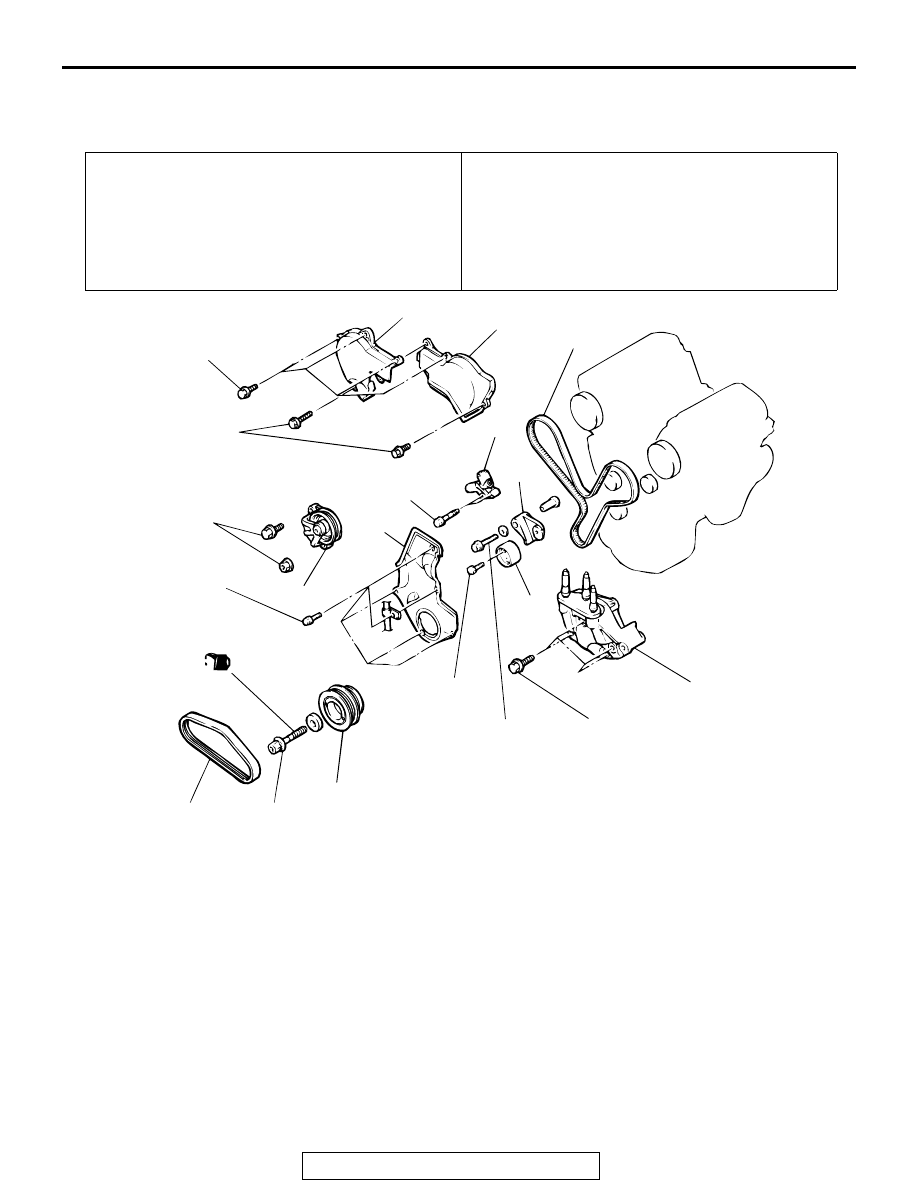
TIMING BELT
REMOVAL AND INSTALLATION
M1112004300731
Required Special Tools:
• MB990767: End Yoke Holder
Pre-removal Operation
• Generator Removal (Refer to GROUP 16, Generator
• Engine Mount Bracket Removal (Refer to GROUP 32,
Engine Mounting
.)
Post-installation Operation
• Engine Mount Bracket Installation (Refer to GROUP 32,
Engine Mounting
.)
• Generator Installation (Refer to GROUP 16, Generator
• Drive Belt Tension Adjustment [Refer to GROUP 00,
Maintenance Service
− Drive Belts (Check Condition)
AC001734 AB
182 ± 4 N·m
134 ± 3 ft-lb
44 ± 5 N·m
33 ± 3 ft-lb
44 ± 10 N·m
33 ± 7 ft-lb
48 ± 6 N·m
36 ± 4 ft-lb
44 ± 10 N·m
33 ± 7 ft-lb
23 ± 3 N·m
17 ± 3 ft-lb
11 ± 1 N·m
96 ± 8 in-lb
14 ± 1 N·m
117 ± 13 in-lb
11 ± 1 N·m
96 ± 8 in-lb
4
5
8
9
11
6
3
10
2
1
7
(ENGINE OIL)
REMOVAL STEPS
1.
DRIVE BELT (POWER
STEERING OIL PUMP)
<<A>>
>>D<<
2.
CRANKSHAFT PULLEY
3.
TENSIONER PULLEY
ASSEMBLY (POWER
STEERING OIL PUMP)
4.
TIMING BELT FRONT UPPER
COVER, RIGHT
5.
TIMING BELT FRONT UPPER
COVER, LEFT
6.
TIMING BELT FRONT LOWER
COVER
>>C<<
7.
ENGINE SUPPORT BRACKET,
RIGHT
<<B>>
>>B<<
8.
TIMING BELT
>>A<<
9.
AUTO-TENSIONER
10. TENSIONER PULLEY
11. TENSIONER ARM
REMOVAL STEPS (Continued)