Mitsubishi Eclipse. Manual - part 104


  Index      Mitsubishi     Mitsubishi Eclipse - service repair manual 2004 year


Search            


Content   ..  102  103  104  105   ..


Mitsubishi Eclipse. Manual - part 104


ON-VEHICLE SERVICE

TSB Revision

ENGINE MECHANICAL <2.4L>

11A-11

6. Set compression gauge to one of the spark plug holes.
7. Crank the engine with the throttle valve fully open and 

measure the compression pressure.

Standard value (at engine speed of 250 

 400 r/min): 

1,275 kPa (185 psi)
Minimum limit (at engine speed of 250 

 400 r/min): 

959 kPa (139 psi)

8. Measure the compression pressure for all the cylinders, and 

check that the pressure differences of the cylinders are 
below the limit.

Limit: 98 kPa (14 psi)

9. If there is a cylinder with compression or a compression 

difference that is outside the limit, pour a small amount of 
engine oil through the spark plug hole, and repeat the 
operations in steps 6 to 8.

(1) If the compression increases after oil is added, the cause 

of the malfunction is a worn or damaged piston ring 
and/or cylinder inner surface.

(2) If the compression does not rise after oil is added, the 

cause is a burnt or defective valve seat, or pressure is 
leaking from the gasket.

10.Connect the crankshaft position sensor connector.
11.Install the spark plugs and spark plug cables.
12.Use the scan tool to erase the diagnostic trouble codes.

NOTE: This will erase the diagnostic trouble code resulting 
from the crankshaft position sensor connector being discon-
nected.

MANIFOLD VACUUM CHECK

M1111002700439

1. Start the engine and allow it to warm up until the 

temperature of the engine coolant reaches 80 

− 95°C (176 − 

203

°F).

2. Connect an engine tachometer.
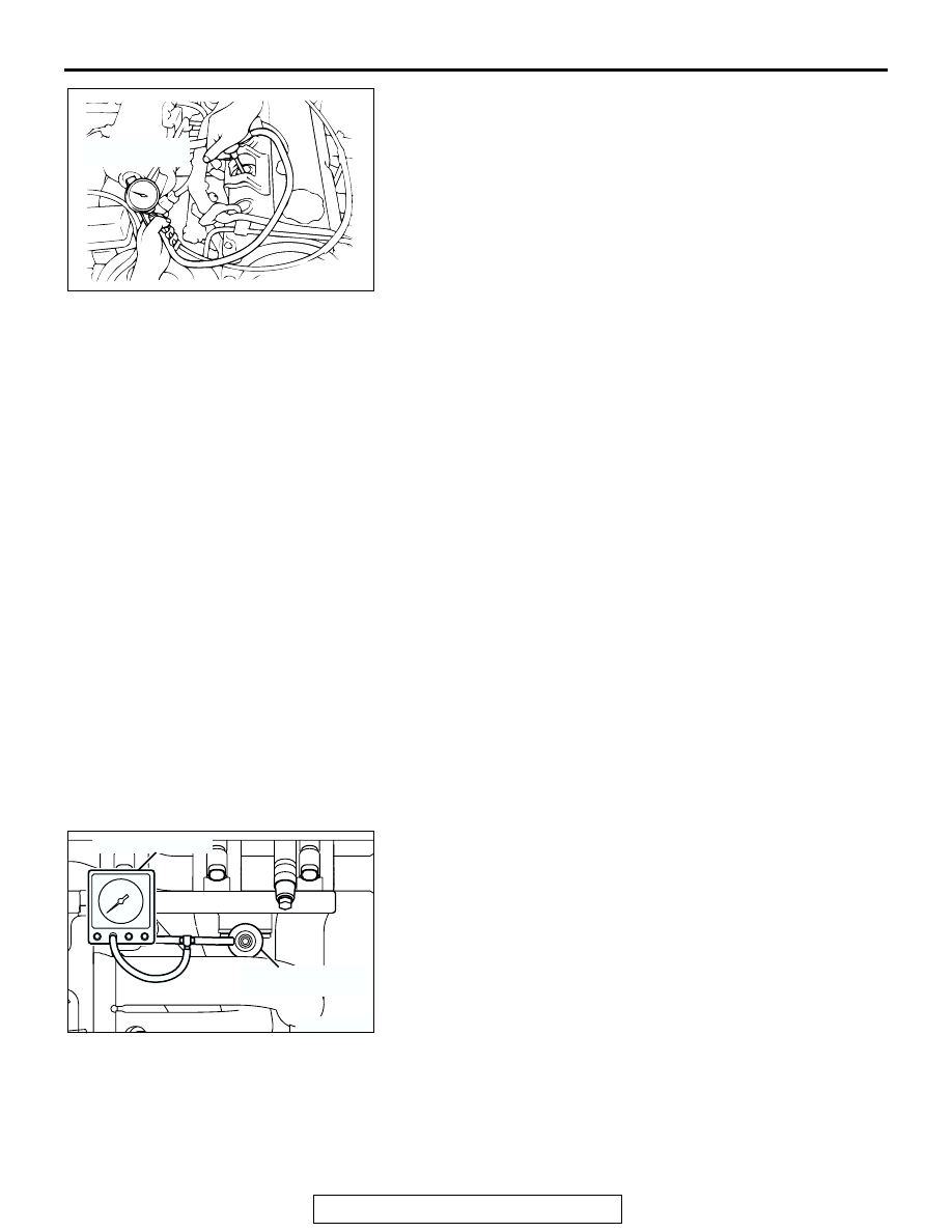
3. Attach a tee-fitting union to the vacuum hose between the 

fuel pressure regulator and the intake manifold plenum, and 
connect a vacuum gauge.

4. Start the engine and check that idle speed is within 

specification. Then check the vacuum gauge reading.

Idle speed: 700 

± 100 r/min

Minimum limit: 60 kPa (18 in Hg)

AKX01178

COMPRESSION
GAUGE

AB

AK300678 AB

VACUUM GAUGE

FUEL PRESSURE 
REGULATOR

ON-VEHICLE SERVICE

TSB Revision

ENGINE MECHANICAL <2.4L>

11A-12

LASH ADJUSTER CHECK

M1111002900381

If an abnormal noise (chattering noise) suspected to be caused 
by malfunction of the lash adjuster is produced immediately 
after starting the engine and does not disappear, perform the 
following check.
NOTE: An abnormal noise due to malfunction of the lash 
adjuster is produced immediately after starting the engine and 
changes with the engine speed, irrespective of the engine load.
If, the abnormal noise is not produced immediately after start-
ing the engine or does not change with the engine speed, or it 
changes with the engine load, the lash adjuster is not the cause 
for the abnormal noise.
NOTE: When the lash adjuster is malfunctioning, the abnormal 
noise is rarely eliminated by continuing the warming-up of the 
engine at idle speed.
However, the abnormal noise may disappear only when seizure 
is caused by oil sludge in the engine whose oil is not main-
tained properly.
1. Start the engine.
2. Check if the abnormal noise produced immediately after 

starting the engine, changes with the change in the engine 
speed.
If the abnormal noise is not produced immediately after 
starting the engine or it does not change with the engine 
speed, the lash adjuster is not the cause for the noise. 
Therefore, investigate other causes. The abnormal noise is 
probably caused by some other parts than the engine proper 
if it does not change with the engine speed. (In this case, the 
lash adjuster is in good condition.)

3. With the engine idling, change the engine load (shift from N 

to D range, for example) to make sure that there is no 
change in the level of abnormal noise.
If there is a change in the level of abnormal noise, suspect a 
tapping noise due to worn crankshaft bearing or connecting 
rod bearing. (In this case, the lash adjuster is in good 
condition.)

4. After completion of warm-up, run the engine at idle to check 

for abnormal noise.
If the noise is reduced or disappears, clean the lash adjuster 
(Refer to GROUP 11B, Engine Overhaul <2.4L> 

− Rocker 

Arms and Camshaft 

− Inspection 

P.11B-27

.) As it is 

suspected that the noise is due to seizure of the lash 
adjuster. If there is no change in the level of the abnormal 
noise, proceed to step 5.

5. Run the engine to bleed the lash adjuster system. (Refer to 

P.11A-12

.)

6. If the abnormal noise does not disappear after air bleeding 

operation, clean the lash adjuster (Refer to GROUP 11B, 
Engine Overhaul <2.4L> 

− Rocker Arms and Camshaft − 

Inspection 

P.11B-27

.)

.

ON-VEHICLE SERVICE

TSB Revision

ENGINE MECHANICAL <2.4L>

11A-13

Bleeding lash adjuster system
NOTE: Parking the vehicle on a grade for a long time may 
decrease oil in the lash adjuster, causing air to enter the high 
pressure chamber when starting the engine.
NOTE: After parking for many hours, oil may run out from the 
oil passage and take time before oil is supplied to the lash 
adjuster, causing air to enter the high pressure chamber.
NOTE: In the above cases, abnormal noise can be eliminated 
by bleeding the lash adjuster system.
1. Check engine oil and add or change oil if required.

NOTE: If the engine oil level is low, air is sucked from the oil 
screen, causing air to enter the oil passage.
NOTE: If the engine oil level is higher than specification, oil 
may be stirred by the crankshaft, causing oil to be mixed 
with a large quantity of air.
NOTE: If oil is deteriorated, air is not easily separated from 
oil, increasing the quantity of air contained in oil.

NOTE: If air mixed with oil enters the high pressure chamber 
inside the lash adjuster from the above causes, air in the 
high pressure chamber is compressed excessively while the 
valve is opened, resulting in an abnormal noise when the 
valve closes.
This is the same phenomenon as that observed when the 
valve clearance has become excessive. The lash adjuster 
can resume normal function when air entered the lash 
adjuster is removed.

2. Idle the engine for one to three minutes to warm it up.
3. Repeat the operation pattern, shown in left figure, at no load 

to check for abnormal noise. (Usually the abnormal noise is 
eliminated after repetition of the operation 10 to 30 times. If, 
however, no change is observed in the level of abnormal 
noise after repeating the operation more than 30 times, 
suspect that the abnormal noise is due to some other 
factors.)

4. After elimination of abnormal noise, repeat the operation 

shown in left figure five more times.

5. Run the engine at idle for one to three minutes to make sure 

that the abnormal noise has been eliminated.

AKX00328

GOOD

MINIMUM

MAXIMUM

AB

AKX00329

HIGH-
PRESSURE
CHAMBER

AB

AKX00330

OPEN THROTTLE
VALVE GRADUALLY

CLOSE
THROTTLE VALVE

APPROXI-
MATELY
3,000 r/min

IDLING
OPERATION

ONCE

15 s

15 s

AIR BLEEDING OPERATION PATTERN

AB

ENGINE ASSEMBLY

TSB Revision

ENGINE MECHANICAL <2.4L>

11A-14

ENGINE ASSEMBLY

REMOVAL AND INSTALLATION

M1112001000742

CAUTION

*: Indicates parts which should be temporarily tightened, and then fully tightened after placing the 
vehicle horizontally and loading the full weight of the engine on the vehicle body.

Pre-removal Operation
• Hood Removal (Refer to GROUP 42, Hood 

P.42-7

.)

• Fuel Line Pressure Reduction [Refer to GROUP 13A, 

On-vehicle Service 

− Fuel Pump Relay Disconnection 

(How to Reduce Pressurized Fuel Lines) 

P.13A-932

.]

• Engine Oil Draining (Refer to GROUP 12, On-vehicle Ser-

vice 

− Engine Oil Replacemen

P.12-3

.)

• Engine Coolant Draining [Refer to GROUP 00, Mainte-

nance Service 

− Engine Coolant (Change) 

P.00-58

.]

• Strut Tower Bar Removal (Refer to GROUP 42, Strut 

Tower Bar 

P.42-11

.)

• Air Cleaner Removal (Refer to GROUP 15, Air Cleaner 

P.15-6

.)

• Reserve Tank and Radiator Removal (Refer to GROUP 

14, Radiator 

P.14-21

.)

• Front Exhaust Pipe Removal (Refer to GROUP 15, 

Exhaust Pipe and Main Muffler 

P.15-22

.)

Post-installation Operation
• Front Exhaust Pipe Installation (Refer to GROUP 15, 

Exhaust Pipe and Main Muffle

P.15-22

.)

• Reserve Tank and Radiator Installation (Refer to GROUP 

14, Radiator 

P.14-21

.)

• Air Cleaner Installation (Refer to GROUP 15, Air Cleaner 

P.15-6

.)

• Strut Tower Bar Installation (Refer to GROUP 42, Strut 

Tower Bar 

P.42-11

.)

• Drive Belt Tension Adjustment [Refer to GROUP 00, 

Maintenance Service 

− Drive Belts (Check Condition) 

P.00-46

.]

• Engine Oil Refilling (Refer to GROUP 12, On-vehicle Ser-

vice 

− Engine Oil Replacement 

P.12-3

.)

• Engine Coolant Refilling [Refer to GROUP 00, Mainte-

nance Service 

− Engine Coolant (Change) 

P.00-58

.]

• Accelerator Cable Adjustment (Refer to GROUP 17, 

On-vehicle Service 

− Accelerator Cable Check and 

Adjustment 

P.17-4

.)

• Hood Installation (Refer to GROUP 42, Hood 

P.42-7

.)

AC106493

O-RING

FUEL RAIL

18

ENGINE OIL

1

18

19

16

2

3

17

4

20

5

6

7

8

14

9

5

10

11

13

12

15

4.9 ± 1.0 N·m
44 ± 8 in-lb

N

12 ± 2 N·m
100 ± 22 in-lb

AB


Content   ..  102  103  104  105   ..