Mitsubishi Colt Ralliart. Manual - part 745


  Index      Mitsubishi     Mitsubishi Colt Ralliart - service repair manual


Search            


Content   ..  743  744  745  746   ..


Mitsubishi Colt Ralliart. Manual - part 745


TROUBLESHOOTING

MULTIPORT FUEL INJECTION (MPI) <4G1>

13B-305

STEP 3. Connector check: A-20 cooling fan 
motor connector

Q: Is the check result normal?

YES : 

Go to Step 4 .

NO : 

Repair or replace.

STEP 4. Check cooling fan motor itself.

• Check cooling fan motor (Refer to GROUP 14 − 

On-vehicle Service 

− Cooling Fan Motor Inspec-

tion 

P.14-9

).

Q: Is the check result normal?

YES : 

Go to Step 5 .

NO : 

Replace fan motor.

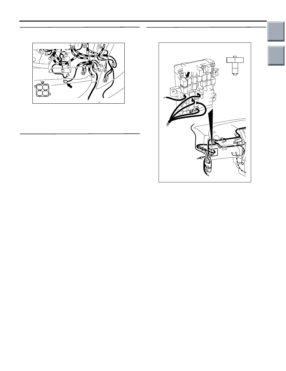
STEP 5. Perform voltage measurement at B-114 
cooling fan control relay (LO) connector.

Disconnect connector and measure at harness side.

• Voltage between terminal No. 3 and earth.

OK: System voltage

Q: Is the check result normal?

YES : 

Go to Step 6 .

NO : 

Check intermediate connector B-108, and 

repair if necessary. If intermediate 
connector is normal, check and repair 
harness between battery and B-114 
(terminal No. 3) cooling fan control relay 
(LO) connector.

• Check power supply line for 

open/short circuit.

AK402108

2 1

4 3

AC

Connector: A-20

Harness side connector

A-20

AK402106

3

2

1

4

AC

Connector: B-114

J/B side 
connector

B-114

Main

Index

Group

TOC

TROUBLESHOOTING

MULTIPORT FUEL INJECTION (MPI) <4G1>

13B-306

STEP 6. Perform voltage measurement at B-114 
cooling fan control relay (LO) connector.

Disconnect connector and measure at harness side.

• Ignition switch: ON

• Voltage between terminal No. 1 and earth.

OK: System voltage

Q: Is the check result normal?

YES : 

Go to Step 8 .

NO : 

Go to Step 7 .

STEP 7. Connector check: B-141 ignition switch 
connector

Q: Is the check result normal?

YES : 

Check intermediate connector B-130, and 

repair if necessary. If the intermediate 
connector is normal, check and repair 
harness between B-141 (terminal No. 4) 
ignition switch connector and B-114 
(terminal No. 1) cooling fan control relay 
(LO) connector.

• Check power supply line for 

open/short circuit.

NO : 

Repair or replace.

AK402106

3

2

1

4

AC

Connector: B-114

J/B side 
connector

B-114

1

2

3

4

5

6

AK402103

Connector: B-141

Harness side 
connector

B-141

AC

AK402106

3

2

1

4

AC

Connector: B-114

J/B side 
connector

B-114

Main

Index

Group

TOC

TROUBLESHOOTING

MULTIPORT FUEL INJECTION (MPI) <4G1>

13B-307

STEP 8. Perform voltage measurement at B-127 
cooling fan control relay (HI) connector.

Disconnect connector and measure at harness side.

• Voltage between terminal No. 3 and earth.

OK: System voltage

Q: Is the check result normal?

YES : 

Go to Step 9 .

NO : 

Check intermediate connector B-108, and 

repair if necessary. If intermediate 
connector is normal, check and repair 
harness between battery and B-127 
(terminal No. 3) cooling fan control relay (HI) 
connector.

• Check power supply line for 

open/short circuit.

STEP 9. Perform voltage measurement at B-127 
cooling fan control relay (HI) connector.

Disconnect connector and measure at harness side.

• Ignition switch: ON

• Voltage between terminal No. 1 and earth.

OK: System voltage

Q: Is the check result normal?

YES : 

Go to Step 11 .

NO : 

Go to Step 10 .

3

2

1

4

AK402107

J/B side 
connector

Connector: B-127
J/B (front side)

AC

B-127

3

2

1

4

AK402107

J/B side 
connector

Connector: B-127
J/B (front side)

AC

B-127

Main

Index

Group

TOC

TROUBLESHOOTING

MULTIPORT FUEL INJECTION (MPI) <4G1>

13B-308

STEP 10. Connector check: B-141 ignition switch 
connector

Q: Is the check result normal?

YES : 

Check intermediate connector B-130, and 

repair if necessary. If the intermediate 
connector is normal, check and repair 
harness between B-141 (terminal No. 4) 
ignition switch connector and B-127 
(terminal No. 1) cooling fan control relay (HI) 
connector.

• Check power supply line for 

open/short circuit.

NO : 

Repair or replace.

STEP 11. Check harness between battery and 
B-114 (terminal No. 3) cooling fan control relay 
(LO) connector.

NOTE: Before checking harness, check intermediate 
connector B-108 and repair if necessary.

• Check power supply line for damage.

Q: Is the check result normal?

YES : 

Go to Step 12 .

NO : 

Repair.

1

2

3

4

5

6

AK402103

Connector: B-141

Harness side 
connector

B-141

AC

3

2

1

4

AK402107

J/B side 
connector

Connector: B-127
J/B (front side)

AC

B-127

AK402106

3

2

1

4

AC

Connector: B-114

J/B side 
connector

B-114

Main

Index

Group

TOC


Content   ..  743  744  745  746   ..