Mitsubishi Colt Ralliart. Manual - part 692
TROUBLESHOOTING
MULTIPORT FUEL INJECTION (MPI) <4G1>
13B-93
FUNCTION
• The engine-ECU controls the injector activation
time.
• The fuel injection amount from the injector
depends on the injector activation time.
TROUBLE JUDGEMENT
Check Conditions
• Engine speed is more than 50 r/min and is less
than 1,000 r/min.
• Throttle position sensor (main) output voltage is
less than 1.0 V.
• Not during fuel cut or forced injector-driving (actu-
ator test)
Judgement Criterion
• Injector coil surge voltage (battery voltage plus 2
V) is not detected for 4 seconds.
PROBABLE CAUSES
• Failed No. 1 injector
• Open/short circuit or damage in No. 1 injector cir-
cuit, or loose connector contact
• Failed engine-ECU
DIAGNOSIS PROCEDURE
STEP 1. M.U.T.-III actuator test
• Item 01: No. 1 injector
OK: Idling state varies.
Q: Is the check result normal?
YES :
Intermittent malfunction (Refer to GROUP
00
− How to Use
Troubleshooting/Inspection Service Points
−
How to Cope with Intermittent Malfunctions
).
NO :
Go to Step 2 .
STEP 2. Connector check: A-102 injector
connector
Q: Is the check result normal?
YES :
Go to Step 3 .
NO :
Repair or replace.
STEP 3. Perform resistance measurement at
A-102 injector connector.
• Disconnect connector, and measure at injector
side.
• Resistance between terminals No. 1 and No. 2.
OK: 10.5
− 13.5 Ω (at 20°C)
Q: Is the check result normal?
YES :
Go to Step 4 .
NO :
Replace No. 1 injector.
STEP 4. Perform voltage measurement at A-102
injector connector.
• Disconnect connector and measure at harness
side.
• Ignition switch: ON
• Voltage between terminal No. 1 and earth.
OK: System voltage
Q: Is the check result normal?
YES :
Go to Step 6 .
NO :
Go to Step 5 .
AK402088
M
1
2
AC
A-102(G)
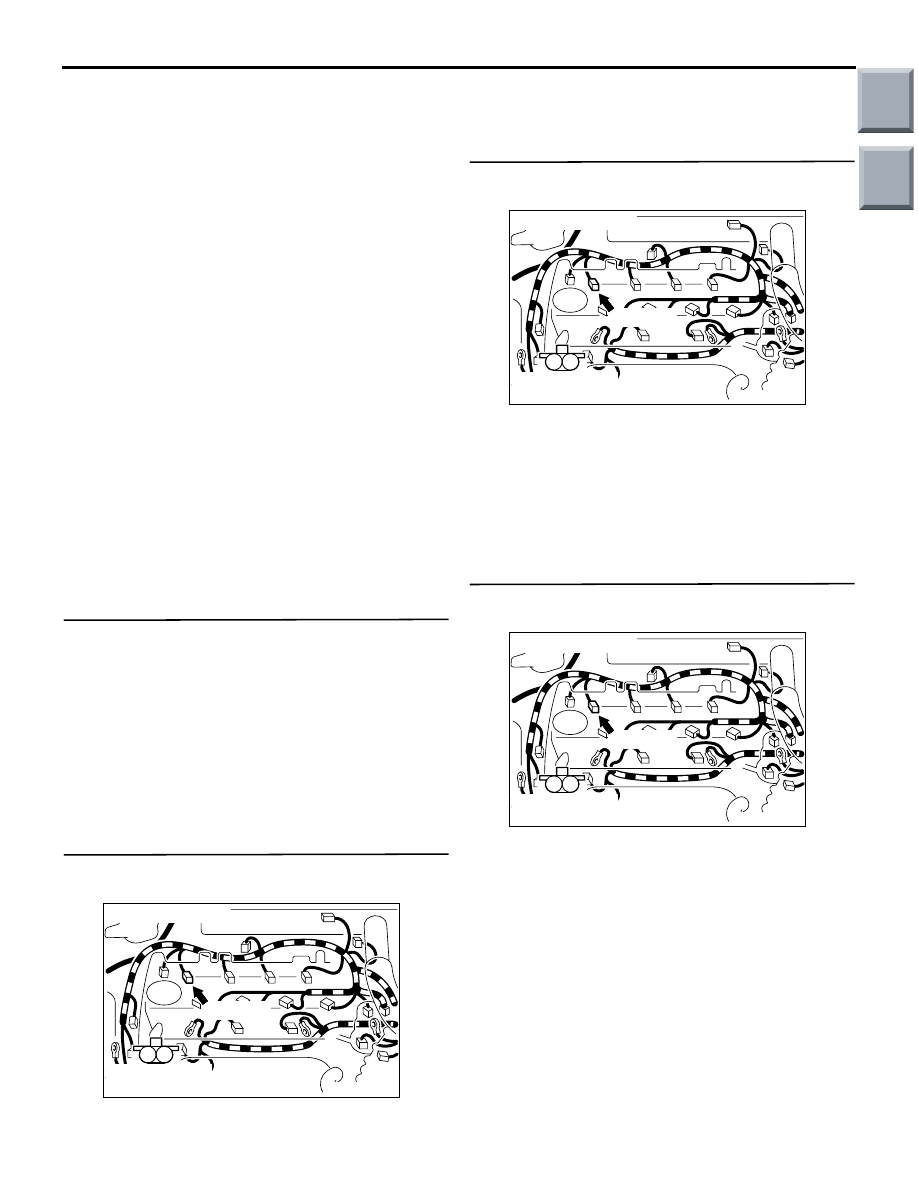
Connector: A-102
Harness side
connector
AK402088
M
1
2
AC
A-102(G)
Connector: A-102
Harness side
connector
AK402088
M
1
2
AC
A-102(G)
Connector: A-102
Harness side
connector
Main
Index
Group
TOC