Mitsubishi Colt Ralliart. Manual - part 654
 

  Index      Mitsubishi     Mitsubishi Colt Ralliart - service repair manual


Search            


Content   ..  652  653  654  655   ..


Mitsubishi Colt Ralliart. Manual - part 654


CYLINDER HEAD GASKET

ENGINE MECHANICAL <4G1>

11C-36

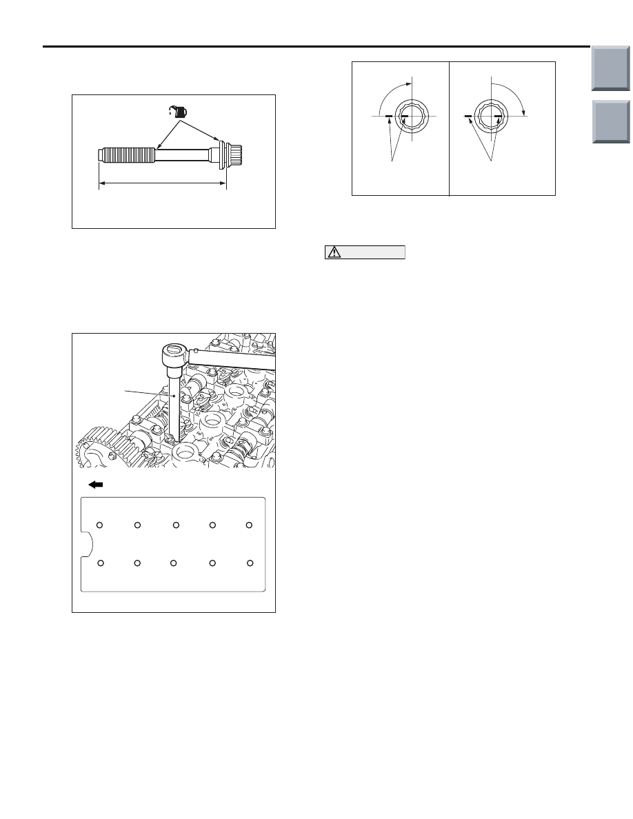
>>B<< CYLINDER HEAD BOLTS 
INSTALLATION

AC102537

A

AB

(Engine oil)

1. Check that the nominal length of each cylinder 

head bolt meets the limit. If it exceeds the limit, 
replace the bolts with a new one.

Limit (A): 103.2 mm

2. Apply a small amount of engine oil to the thread of 

the bolts and to the washers.

AC207640

1

2

3

4

5

6

7

8

9

10

AB

MB991653

Engine front

3. Use special tool cylinder head bolt wrench 

(MB991653) to tighten the cylinder head bolts in 
the following procedures.
(1) Tighten the bolts to 49 

± 2 N⋅m in the order 

shown.

(2) Loosen the bolts fully in the reverse sequence 

to that shown.

(3) Tighten the bolts to 20 

± 2 N⋅m in the order 

shown.

AC102331AB

Paint marking

90˚

90˚ 

Step (4)

Step (5)

Paint marking

(4) Apply a paint mark to the heads of the cylinder 

head bolts and cylinder head, then tighten 90 
degree angle as shown.

CAUTION

• The bolt is not tightening sufficiently if the 

tightening angle is less than a 90 degree 
angle.

• If the tightening angle exceeds the standard 

specification, remove the bolt and start over 
from step 1.

(5) Tighten in a 90 degree angle as shown in the 

instructions of the figure, then check to see 
that the paint mark on the head of the cylinder 
head bolts and the paint mark on the cylinder 
head is on a linear line.

Main

Index

Group

TOC

TIMING BELT

ENGINE MECHANICAL <4G1>

11C-37

TIMING BELT

REMOVAL AND INSTALLATION

M1112004301637

Pre-removal Operation
• Front Under Cover Panel Removal (Refer to GROUP 51, 

Front Bumper Assembly and Radiator Grille 

P.51-2

).

• Side Under Cover Panel (RH) Removal (Refer to GROUP 

51, Front Bumper Assembly and Radiator Grill

P.51-2

).

• Crankshaft Pulley Removal (Refer to 

P.11C-17

).

Post-installation Operation
• Crankshaft Pulley Installation (Refer to 

P.11C-17

).

• Drive Belt Tension Check and Adjustment (Refer to 

P.11C-8

).

• Side Under Cover Panel (RH) Installation (Refer to 

GROUP 51, Front Bumper Assembly and Radiator Grille 

P.51-2

).

• Front Under Cover Panel Installation (Refer to GROUP51, 

Front Bumper Assembly and Radiator Grille 

P.51-2

).

AC402665AB

1

11 ± 1 N·m

2

3

4

5

6

7

8

9

10

11

12

11 ± 1 N·m

9.0 ± 2.0 N·m

11 ± 1 N·m

44 ± 10 N·m

23 ± 3 N·m

48 ± 6 N·m

9.0 ± 2.0 N·m

Removal steps 

1.

A/C compressor connector

2.

Crank angle sensor connector

3.

Oxygen sensor connector

4.

Timing belt upper cover

Engine mounting insulator (Refer to 
GROUP 32, Engine Mounting 

P.32-6

).

5.

Earth cable connection

6.

Water pump pulley

7.

Timing belt lower cover

>>

D

<<

Valve timing belt tension 
adjustment <Installation only>

<<

A

>>

>>

C

<<

8.

Valve timing belt

>>

B

<<

9.

Timing belt tensioner pulley

10. Timing belt tensioner arm

>>

A

<<

11. Timing belt tensioner adjuster
12. Timing belt idler pulley

Removal steps (Continued)

Main

Index

Group

TOC

TIMING BELT

ENGINE MECHANICAL <4G1>

11C-38

REMOVAL SERVICE POINT
<<A>> VALVE TIMING BELT REMOVAL

CAUTION

Be sure to use special tool crankshaft sprocket 
spacer (MD998769) when installing the crank-
shaft pulley centre bolt to the crankshaft. If the 
bolt is installed directly to the crankshaft, the tip 
of the bolt and the thread of the crankshaft may 
be damaged.

AC207170

AB

Crankshaft camshaft 
drive sprocket

MD998769

1. Set the special tool, the crankshaft pulley washer 

and the crankshaft pulley centre bolt to the 
crankshaft camshaft drive sprocket.

CAUTION

Never turn the crankshaft anti-clockwise.

AC205412

AB

Timing mark

2. Turn the crankshaft clockwise, align each timing 

mark to set No.1 cylinder to TDC of its 
compression stroke.

AC207160

AB

MD998738

Alternator

3. Remove the timing belt under cover rubber plug 

and then set special tool adjusting bolt 
(MD998738).

AC208791

AB

Timing belt 
tensioner arm

MD998738

4. Screw in the special tool with hands until it 

contacts the timing belt tensioner arm.

CAUTION

The special tool can be gradually installed at a 
rate of a 30 degree turn per second. If it is 
screwed in all at once, the timing belt tensioner 
adjuster rod will not easily retract and the special 
tool may bend.

AC207162

AC

Timing belt 
tensioner adjuster 

Wire or pin

5. Gradually screw in the special tool. Then align the 

timing belt tensioner adjuster rod set hole with the 
timing belt tensioner adjustor cylinder set hole, 
and insert a wire or a pin.

CAUTION

To reuse the valve timing belt, draw an arrow 
indicating the rotating direction (clockwise) on 
the back of the belt using chalk, etc.
6. After removal of the special tool, loosen the timing 

belt tensioner pulley mounting bolts and remove 
the valve timing belt.

Main

Index

Group

TOC

TIMING BELT

ENGINE MECHANICAL <4G1>

11C-39

INSTALLATION SERVICE POINTS
>>A<< TIMING BELT TENSIONER 
ADJUSTER INSTALLATION

1. Set according to the following procedures when 

the timing belt tensioner adjuster rod is fully 
extended.

CAUTION

If the compression is too fast the procedure may 
damage the rod. Make a point to slowly and thor-
oughly compress.

AC207761

B

A

AB

(1) Slowly compress the timing belt tensioner 

adjuster rod using a press or vice, then align 
the set hole A of the rod with set hole B of the 
timing belt tensioner adjuster cylinder.

AC207762AC

Wire or pin

(2) Insert a wire or pin in the set hole aligned.

NOTE: . When replacing the timing belt ten-
sioner adjuster with new parts, the timing belt 
tensioner adjuster is set with a pin.

2. Install the timing belt tensioner adjuster to the 

engine and then tighten the mounting bolts to the 
specified torque. Do not remove the wire or pin 
until the tension of the valve timing belt is 
adjusted. 

Tightening torque: 23 

± 3 Nm

>>B<< TIMING BELT TENSIONER 
PULLEY INSTALLATION

AC102336AB

Timing belt tensioner
pulley holes  

Temporarily tighten the timing belt tensioner pulley 
as shown.

Main

Index

Group

TOC


Content   ..  652  653  654  655   ..