Mitsubishi Colt Ralliart. Manual - part 627
TROUBLESHOOTING
ACTIVE STABILITY CONTROL SYSTEM (ASC)
35C-53
Code No. C1278: Valve relay stuck OFF
CAUTION
If there is any problem in the CAN bus lines, an
incorrect diagnosis code may be set. Prior to this
diagnosis, always diagnose the CAN bus lines.
OPERATION
• ASC-ECU contains the power supply circuit (ter-
minal No. 44) for the solenoid valve. The solenoid
valve is energised by the valve relay, which is
incorporated in ASC-ECU.
• The valve relay, which is incorporated in
ASC-ECU, is always energising the solenoid
valve unless the initial check is in progress when
the ignition switch is turned on, or the recurrent
system check is in progress.
DIAGNOSIS CODE SET CONDITIONS
When the solenoid valve is not energised even after
the valve relay is turned ON, the ECU determines
that the valve relay stuck OFF and sets this diagno-
sis code.
PROBABLE CAUSES
Current trouble
• Damaged wiring harness and connectors
• The ABS-ECU is defective.
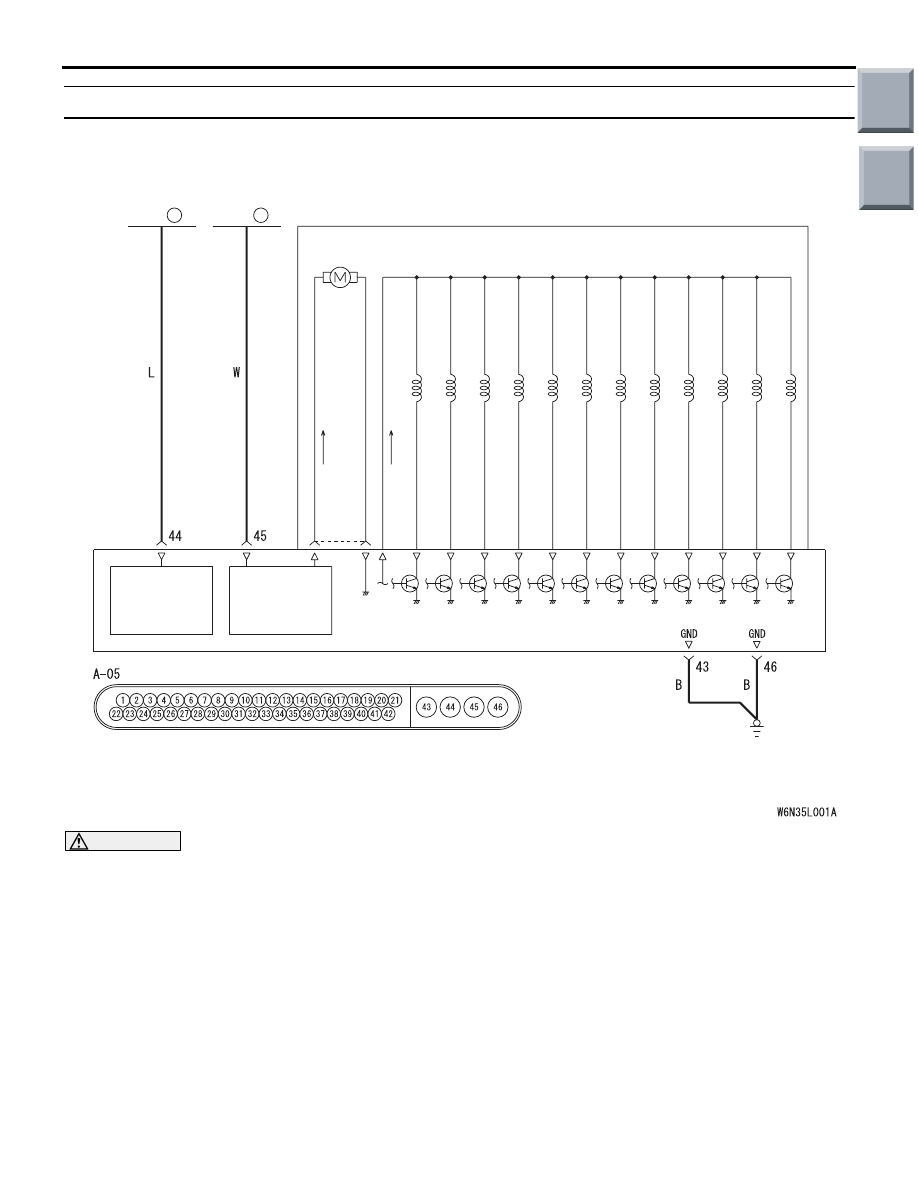
Hydraulic unit (Motor and Solenoid Valve) Circuit
Wire colour code
B : Black LG : Light green G : Green L : Blue W : White Y : Yellow SB : Sky blue
BR : Brown O : Orange GR : Grey R : Red P : Pink V : Violet PU : Purple
FUSIBLE
LINK
FUSIBLE
LINK
3
5
ASC-ECU
HYDRAULIC UNIT
SOLENOID
VALVE
POWER
SOURCE
ABS SOLENOID VALVE
MOTOR
MOTOR
POWER
SOURCE
Main
Index
Group
TOC