Mitsubishi Colt Ralliart. Manual - part 573
TROUBLESHOOTING
SUPPLEMENTAL RESTRAINT SYSTEM (SRS)
52B-130
DIAGNOSIS PROCEDURE
STEP 1. Check the harness wires for open circuit
or short circuit between SRS-ECU connector
B-34 (terminal No.40 and 42) and side impact
sensor (RH) connector C-27 (terminal No.1 and
2).
Q: Are the harness wires between SRS-ECU
connector B-34 (terminal No.40 and 42) and side
impact sensor (RH) connector C-27 (terminal No.1
and 2) in good condition?
YES : .
Go to Step 2.
NO : .
Repair the harness wires between
SRS-ECU connector B-34> (terminal No.40
and 42) and side impact sensor (RH)
connector C-27 (terminal No.1 and 2).
STEP 2. Check the side impact sensor (RH)
(front). (M.U.T.-III diagnosis code)
(1) Disconnect the negative battery terminal.
(2) Replace the side impact sensor (RH) (front) with
the side impact sensor (LH) (front).
(3) Connect the negative battery terminal.
(4) Erase diagnosis code from memory, and check
the diagnosis code.
Q: Is diagnosis code 94 set?
YES :
Replace the SRS-ECU (Refer to
).
NO :
Replace the side impact sensor (LH) (front)
with a new one (Refer to
Step 3 .
STEP 3. Check whether the diagnosis code is
reset.
Q: Is diagnosis code 94 set?
YES :
Replace the SRS-ECU (Refer to
).
NO :
An intermittent malfunction is suspected
(Refer to GROUP 00, How to Cope with
Intermittent Malfunction
).
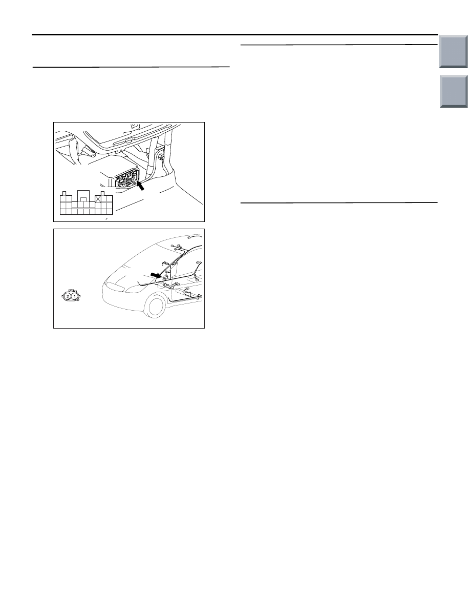
AC206285
AG
B-34 (Y)
Connector: B-34
Harness side
connector
(rear view)
343536373839404142
252627282930313233
2122
2324
AC401057
AK
Connector: C-27
C-27 (Y)
Harness side
(front view)
Main
Index
Group
TOC