Mitsubishi Colt Ralliart. Manual - part 544
TROUBLESHOOTING
SUPPLEMENTAL RESTRAINT SYSTEM (SRS)
52B-14
DIAGNOSTIC TROUBLE CODE
PROCEDURES
Code No.1A Front impact sensor LH system (short circuit in the sensor)
Code No.1B Front impact sensor LH system (open circuit in the sensor)
Code No.1C Front impact sensor LH system (short circuited in the power supply)
Code No.1D Front impact sensor LH system (short circuited in the earth)
Code No.2A Front impact sensor RH system (short circuit in the sensor)
Code No.2B Front impact sensor RH system (open circuit in the sensor)
Code No.2C Front impact sensor RH system (short circuited in the power supply)
Code No.2D Front impact sensor RH system (short circuited in the earth)
OPERATION
• When the left and right front impact sensors
detect a collision, the switches inside the sensors
turn ON.
• SRS-ECU judges how severe a collision is by
detecting signals from the front impact sensors
and the front air bag analogue G-sensor. If the
impact is over a predetermined level, the
SRS-ECU sends an ignition signal. At this time, if
the front air bag safing G-sensor is on, the SRS
air bag will inflate.
AC510220
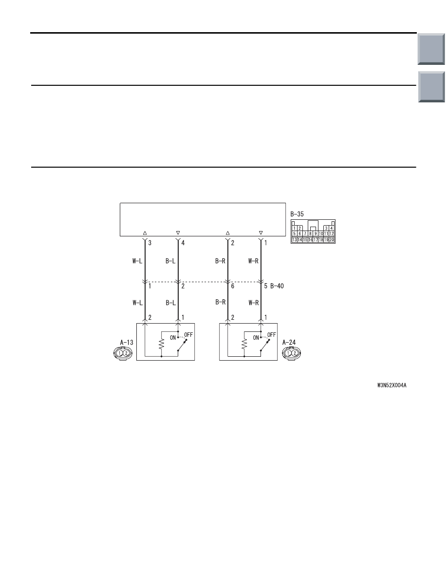
SRS-ECU
FRONT IMPACT
SENSOR (RH)
FRONT IMPACT
SENSOR (LH)
Wire colour code
B : Black LG : Light green G : Green L : Blue W : White Y : Yellow SB : Sky blue
BR : Brown O : Orange GR : Grey R : Red P : Pink V : Violet
Front Impact Sensor Circuit
AB
Main
Index
Group
TOC