Mitsubishi Colt Ralliart. Manual - part 454


  Index      Mitsubishi     Mitsubishi Colt Ralliart - service repair manual


Search            


Content   ..  452  453  454  455   ..


Mitsubishi Colt Ralliart. Manual - part 454


TROUBLESHOOTING

POWER STEERING

37-83

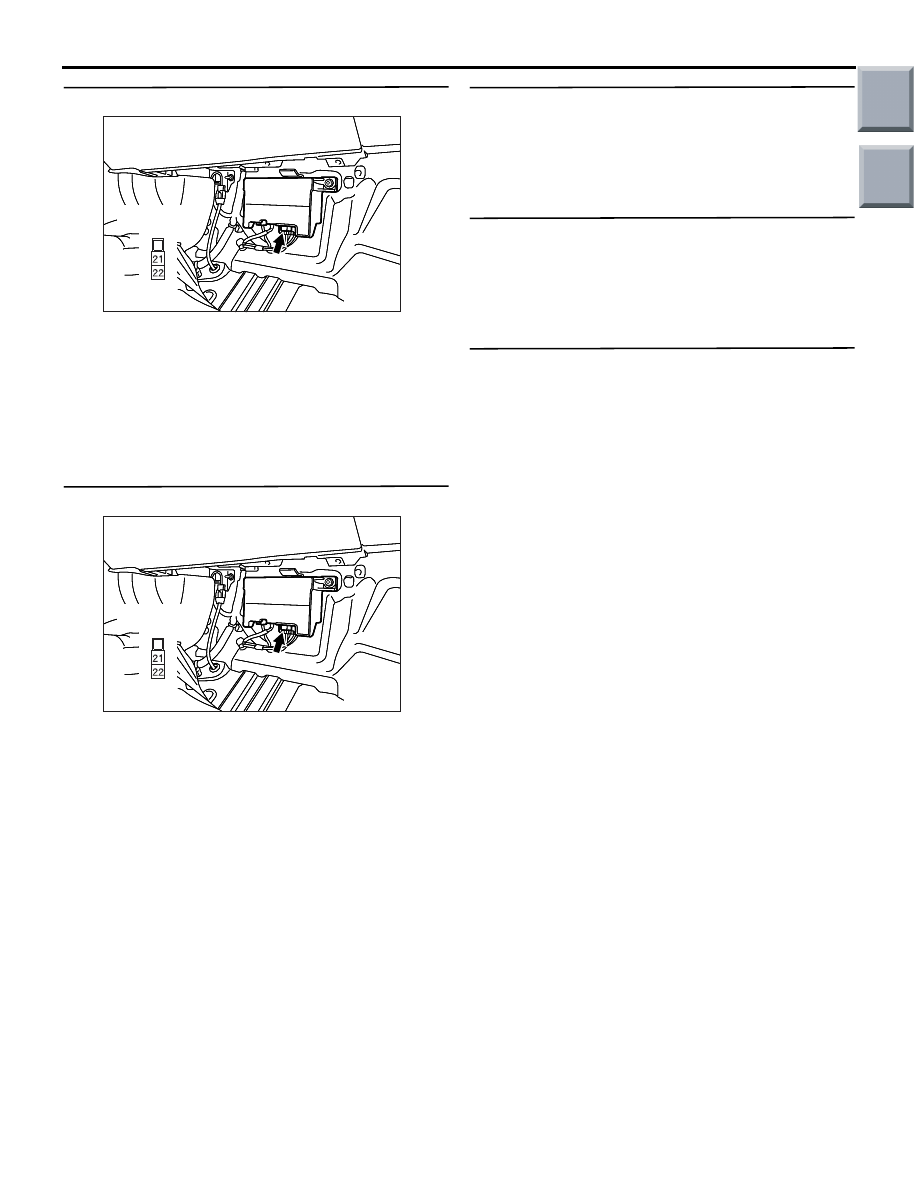
STEP 7. Check the harness wires.

AC314189

AC314189

AC314189AG

Connector: B-38

Harness side

Harness wire between electric power steering-ECU 

connector B-38 and fusible link No.22

Check the harness wire above for damage or other 
problem.

Q: Is the harness wire in good condition?

YES : 

Go to Step 11.

NO : 

Repair the harness wire.

STEP 8. Check the harness wires.

AC314189

AC314189

AC314189AG

Connector: B-38

Harness side

Harness wire between electric power steering-ECU 

connector B-38 and body earth

Check the harness wire above for damage or other 
problem.

Q: Is the harness wire in good condition?

YES : 

Go to Step 11.

NO : 

Repair the harness wire.

STEP 9. Check the battery
Refer to GROUP 54A, Battery Test 

P.54A-5

.

Q: Is the battery in good condition?

YES : 

Go to Step 10.

NO : 

Charge or replace the battery.

STEP 10. Check the charging system.
Refer to GROUP 16, Charging System 

P.16-11

.

Q: Is the charging system in good condition?

YES : 

Go to Step 11.

NO : 

Repair or replace the charging system.

STEP 11. Retest the system.

Q: Is the check result normal?

YES : 

The malfunction is intermittent. Refer to 

GROUP 00, How to Use 
Troubleshooting/Inspection Service Points 

− 

How to Cope with Intermittent Malfunction 

P.00-13

.

NO : 

Replace the electric power steering-ECU 
(Refer to 

P.37-102

). 

Main

Index

Group

TOC

TROUBLESHOOTING

POWER STEERING

37-84

DATA LIST REFERENCE TABLE

M1372007700062

The following items can be read by the M.U.T.-III 
from the electric power steering-ECU input data.

When the system is normal.

Item No.

Check item

Check condition

Normal condition

01

Torque sensor 
(main)

• Start the engine.

• Turn the steering wheel 

with a vehicle 
stationary.

Centre position

Approximately 2500 mV

Steering wheel 
turned to right

2500 

− 4500 mV

Steering wheel 
turned to left

500 

− 2500 mV

02

Torque sensor 
(sub)

• Start the engine.

• Turn the steering wheel 

with a vehicle 
stationary.

Centre position

Approximately 2500 mV

Steering wheel 
turned to right

2500 

− 500 mV

Steering wheel 
turned to left

4500 

− 2500 mV

03

Torque sensor 
supply voltage*

Start the engine.

3750 

− 4250 mV

05

Motor current

• Start the engine.

• Turn the steering wheel to the left and 

right with a vehicle stationary.

Approximately 50 A or 
less
(When the steering wheel 
is not operated, 
approximately 0 V)

06

Motor current 
(desired value)

• Start the engine.

• Turn the steering wheel to the left and 

right with a vehicle stationary.

Approximately 50 A or 
less
(When the steering wheel 
is not operated, 
approximately 0 V)

07

Assist limit 
current (limit 
value)

• Start the engine.

• Turn the steering wheel to the left and 

right with a vehicle stationary.

Approximately 50 A or 
less
(After at least 10 minutes 
without operating the 
steering wheel, 
approximately 50 A)

10

Relay voltage

• Start the engine.

• Turn the steering wheel to the left and 

right with a vehicle stationary.

B+ (approximately 12 V) 
or less

11

Vehicle speed

Perform a test run of the vehicle.

Speedometer displayed 
value and M.U.T.-III 
displayed value agree with 
each other.

12

Engine speed

Start the engine.

Tachometer displayed 
value and M.U.T.-III 
displayed value agree with 
each other.

Main

Index

Group

TOC

TROUBLESHOOTING

POWER STEERING

37-85

NOTE: Item No.13 (idle-up relay) is displayed on 
M.U.T.-III. In this case, however, the idle-up signal is 
not accepted by the engine-ECU, and the idle speed 
will not actually increase. Therefore, the item No.13 
is excluded from the above table.

NOTE: *: Torque sensor is supplied either with 3 V or 
8 V. Only the 8 V side of the torque sensor power 
supply can be monitored by M.U.T.-III as service data 
(Output is 8V x 0.5). Even though the 8 V-ide torque 
sensor power supply is normal, diagnosis code 
C1514 (abnormal torque sensor power supply) is dis-
played if any malfunction occurs in the 3 V-side 
power supply.

When the electric power steering-ECU shut off electric power steering system opera-
tion.

When the diagnosis system stops the electric power 
steering-ECU, the M.U.T.-III display data will be 
unreliable.

ACTUATOR TEST REFERENCE TABLE

M1372007800047

The M.U.T.-III activates the following actuators for 
testing.
NOTE: If the electric power steering-ECU runs down, 
actuator testing cannot be carried out.

NOTE: Actuator testing is only possible when the 
vehicle is stationary.

No.

Item

01

Vehicle speed 5km/h

Forced vehicle speed sensitivity

02

Vehicle speed 25km/h

03

Vehicle speed 50km/h

04

Vehicle speed 75km/h

05

Vehicle speed 100km/h

06

Forced idle up ON

Forced idle up ON
No idle-up

00

Forced idle up OFF (Plant)

14

Fail-safe relay

Stop the engine. (Ignition switch: ON)

OFF

Start the engine, and let it idle.

ON

15

Ignition switch 
key signal

Ignition switch: from ON to OFF

OFF

Ignition switch: ON

ON

Item No.

Check item

Check condition

Normal condition

Main

Index

Group

TOC

TROUBLESHOOTING

POWER STEERING

37-86

CHECK AT ELECTRIC POWER STEERING-ECU

M1372008000066

AC208338

1 2

5 6

3 4

8

7

1112

1516

1314

18

17

21
22

31
32

AD

B-37

B-37-1

B-38

B-38-1

Terminal 
No.

Check item

Checking requirement

Normal condition

5

Ignition key signal

Ignition switch: ON

System voltage

Ignition switch: OFF

0 V

12

Torque sensor main signal

• Start the engine.

• Turn the steering wheel to the 

left and right with a vehicle 
stationary.

0.5 

− 4.5 V

(When the steering 
wheel is not operated, 
approximately 2.5 V)

13

Torque sensor GND

Always

0 V

14

8 V-power supply to the torque 
sensor

Start the engine, and let it idle.

7.6 

− 8.4 V

15

Torque sensor shield earth

Always

0 V

16

Torque sensor sub signal

• Start the engine.

• Turn the steering wheel to the 

left and right with a vehicle 
stationary.

0.5 

− 4.5 V

(When the steering 
wheel is not operated, 
approximately 2.5 V)

18

3 V-power supply to torque sensor

Ignition switch: ON

2.93 

− 3.07 V

21

Earth

Always

0 V

22

Battery power supply

Always

System voltage

31

Motor (L)

• Start the engine.

• Turn the steering wheel to the 

left with a vehicle stationary.

Approximately 50 A or 
less

32

Motor (R)

• Start the engine.

• Turn the steering wheel to the 

right with a vehicle stationary.

Approximately 50 A or 
less

Main

Index

Group

TOC


Content   ..  452  453  454  455   ..