Mitsubishi Colt Ralliart. Manual - part 440


  Index      Mitsubishi     Mitsubishi Colt Ralliart - service repair manual


Search            


Content   ..  438  439  440  441   ..


Mitsubishi Colt Ralliart. Manual - part 440


TROUBLESHOOTING

POWER STEERING

37-27

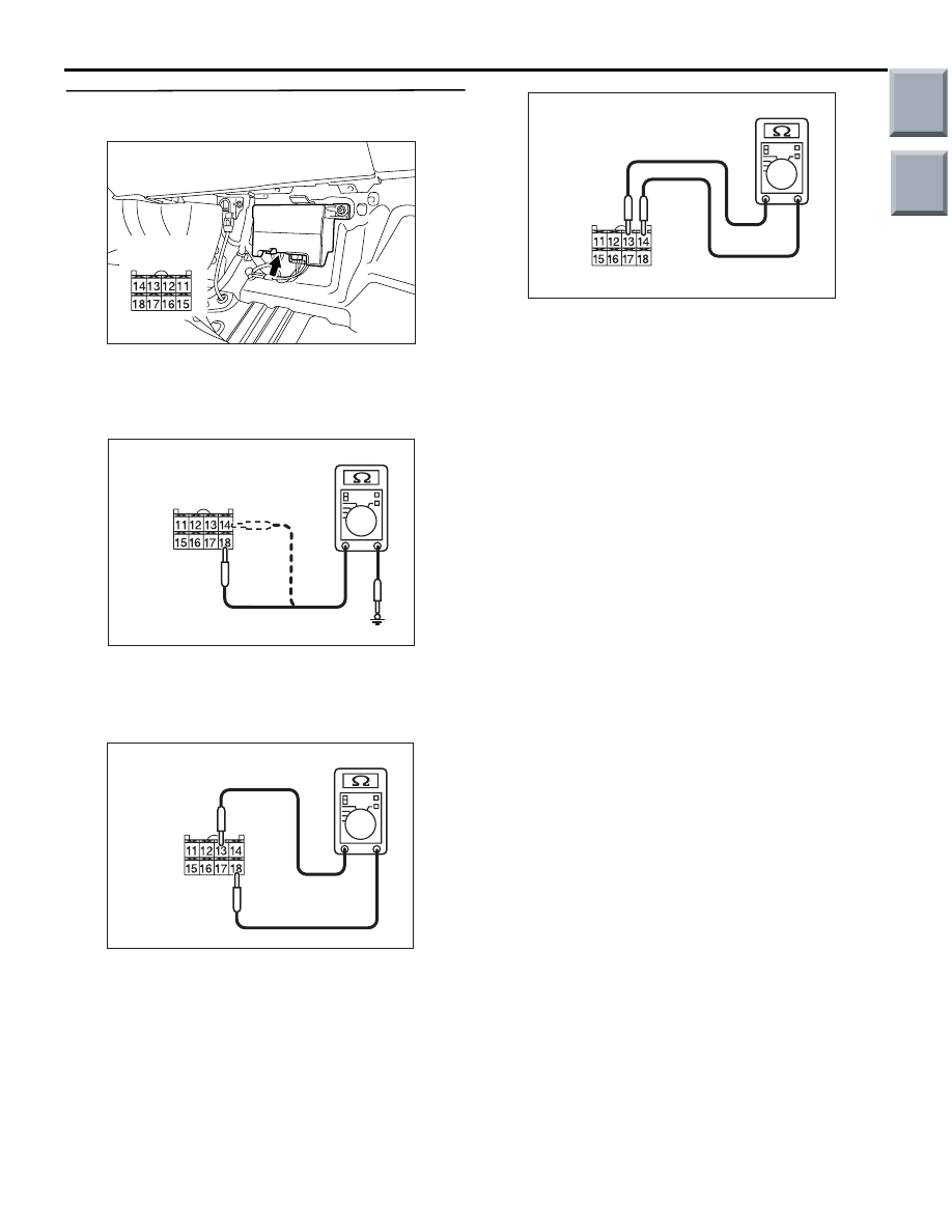
STEP 3. Check the power supply lines inside the 
torque sensor for open circuit.

AC314189AD

Connector: B-37-1

Harness side

Disconnect electric power steering-ECU connector 
B-37-1, and measure the resistances between the 
connector-side terminals of the steering gear and 
linkage assembly.

AC313972 CU

Harness side
connector B-38-1
(Rear view)

Between connector B-37-1 terminal 18 and body 

earth

• Between connector B-37-1 terminal 14 and body 

earth

AC400139AB

Harness side
connector B-37-1
(Rear view)

Between connector B-37-1 terminals 18 and 13

AC400139AC

Harness side
connector B-37-1
(Rear view)

Between connector B-37-1 terminals 14 and 13

OK: 100 

 or more

Q: Is the check result normal?

YES : 

Go to Step 4.

NO : 

Replace the steering gear and linkage 
assembly (Refer to 

P.37-96

).

Main

Index

Group

TOC

TROUBLESHOOTING

POWER STEERING

37-28

STEP 4. Check whether the diagnosis code is 
reset.

AC206895

AC

Diagnosis

connector

MB991827

MB991824 

MB991910

CAUTION

Before connecting or disconnecting the 
M.U.T.-III, turn the ignition switch to the "LOCK" 
(OFF) position.
Check again if the diagnosis code is set.
(1) Turn the ignition switch to the "ON" position.

(2) Erase the diagnosis code.
(3) Turn the ignition switch to the "LOCK" (OFF) 

position.

(4) Turn the ignition switch to the "ON" position.
(5) Start the engine, and check the diagnosis code.
(6) Turn the ignition switch to the "LOCK" (OFF) 

position.

(7) Disconnect M.U.T.-III.

Q: Is diagnosis code C1514 set?

YES : 

Replace the electric power steering-ECU 

(Refer to 

P.37-102

). 

NO : 

The malfunction is intermittent. Refer to 
GROUP 00, How to Use 
Troubleshooting/Inspection Service Points 

− 

How to Cope with Intermittent Malfunction 

P.00-13

.

Main

Index

Group

TOC

TROUBLESHOOTING

POWER STEERING

37-29

Code No.C1521 Vehicle speed sensor input malfunction

CAUTION

• If the electric power steering-ECU sets diagnosis code No.C1521, diagnose the CAN bus lines. If 

there is any fault in the CAN bus lines, an incorrect diagnosis code may be set.

ENGINE-CVT-ECU

DIAGNOSIS
CONNECTOR

FRONT SIDE

COMBINATION
METER

ABS-ECU

CAN Communication Circuit

Wire colour code
B : Black
LG : Light green
G : Green
L: Blue
W : White
Y: Yellow
SB : Sky blue
BR : Brown
O : Orange
GR : Gray
R : Red
P : Pink
V : Violet

ELECTRIC POWER 
STEERING-ECU

Whenever the ECU is replaced, ensure that the communication circuit is normal.

Main

Index

Group

TOC

FRONT WHEEL SPEED SENSOR

(LH)

(RH)

(LH)

(RH)

ABS-ECU

REAR WHEEL SPEED SENSOR

Wire colour code
B : Black     LG : Light green     G : Green     L : Blue     W : White     Y : Yellow     SB : Sky blue
BR : Brown     O : Orange     GR : Gray     R : Red     P : Pink     V : Violet

 Wheel Speed Sensor Circuit

TROUBLESHOOTING

POWER STEERING

37-30

DIAGNOSIS CODE SET CONDITIONS

This diagnosis code is set in the following case:

• If the system receives an abnormal vehicle speed 

signal and the microprocessor determines that 
the vehicle speed measurement system is defec-
tive. 
Criteria for judging malfunction

• The vehicle speed is 30 km/h or more and the 

vehicle speed signal is 0 km/h

PROBABLE CAUSES

• Defective wire(s) or connector(s) in the wiring 

harness between the ABS-ECU and the wheel 
speed sensor

• Malfunction of the wheel speed sensor or vehicle 

speed detection encoder

• Defective power supply to the ABS-ECU

• Malfunction of the ABS-ECU

• Malfunction of the electric power steering-ECU

Main

Index

Group

TOC


Content   ..  438  439  440  441   ..