Mitsubishi Colt Ralliart. Manual - part 369


  Index      Mitsubishi     Mitsubishi Colt Ralliart - service repair manual


Search            


Content   ..  367  368  369  370   ..


Mitsubishi Colt Ralliart. Manual - part 369


INPUT SIGNAL PROCEDURES

SMART WIRING SYSTEM (SWS) NOT USING SWS MONITOR

54B-220

DIAGNOSIS PROCEDURE

Step 1. Pulse check
Check the input signal from the driver's door switch.

OK: The M.U.T.-III sounds or the voltmeter 
needle fluctuates.

Q: Are the check result normal?

All the signals are received normally. : 

Go to Step 

2.

The driver’s door switch signals is not received. : 

Refer to Inspection Procedure N-3 "The 
driver's door switch signal is not received 

P.54B-204

."

The passenger’s door switch signals is not 
received. : 

Refer to inspection procedure N-14 

"The passenger's door switch signal is not 
received 

P.54B-231

."

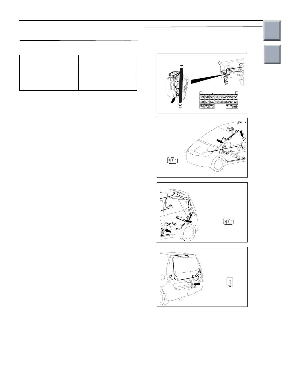
Step 2. Connectors check: C-29 (front: RH), C-19 
(front: LH), C-08 (rear: RH) or C-14 (rear: LH) door 
switch connectors or E-08 tailgate switch 
connector, and B-133 ETACS-ECU connector

Q: Is the check result normal?

YES : 

Go to Step 3.

NO : 

Repair the defective connector.

System switch

Check conditions

Driver's door switch

When the driver's door is 
opened

Passenger’s door switch When the passenger's 

door is opened

AC313826AC

B-133 (GR)

Connector: B-133

Harness side

Junction block (Rear view)

AC401057

AG

Connectors: C-08, C-29

Harness side

C-08, C-29

C-08

C-29

AC401059

Connectors: C-14, C-19

AE

C-14, C-19

C-14

C-19

Harness side

AC401046

Connector: E-08

AE

Harness side

E-08 (B)

Main

Index

Group

TOC

INPUT SIGNAL PROCEDURES

SMART WIRING SYSTEM (SWS) NOT USING SWS MONITOR

54B-221

Step 3. Check the installation condition.
Check that the door switch is installed on the body 
correctly.

Q: Is the check result normal?

YES : 

Go to Step 4.

NO : 

Correct the installation condition.

Step 4.Check the door switch.
Refer to GROUP 42 

− Door 

P.42-39

.

Q: Is the check result normal?

YES : 

Go to Step 5.

NO : 

Replace the door switch.

Step 5. Check the wiring harness from terminal 
No.2 of the C-29 (front: RH), C-19 (front: LH), C-08 
(rear: RH) or C-14 (rear: LH) door switch 
connector or terminal No.1 of the E-08 tailgate 
switch connector to terminal No.61 of the B-133 
ETACS-ECU connector.

AC313826AC

B-133 (GR)

Connector: B-133

Harness side

Junction block (Rear view)

AC401057

AG

Connectors: C-08, C-29

Harness side

C-08, C-29

C-08

C-29

AC401059

Connectors: C-14, C-19

AE

C-14, C-19

C-14

C-19

Harness side

AC401046

Connector: E-08

AE

Harness side

E-08 (B)

Main

Index

Group

TOC

INPUT SIGNAL PROCEDURES

SMART WIRING SYSTEM (SWS) NOT USING SWS MONITOR

54B-222

NOTE: 

Prior to the wiring harness inspection, check interme-
diate connector C-12 <tailgate> and junction block 
connector B-23 or B-24 <RH> and repair if neces-
sary.

• Check the input line for open circuit.

Q: Is the check result normal?

YES : 

Go to Step 6.

NO : 

Repair the wiring harness between each of 
the door switches and the ETACS-ECU.

Step 6. Retest the system.
Check that all the all door switch signals are received 
normally.

Q: Is the check result normal?

YES : 

The trouble can be an intermittent 

malfunction (Refer to GROUP 00 

− How to 

use Troubleshooting/inspection Service 
Points 

− How to Cope with Intermittent 

Malfunction 

P.00-13

).

NO : 

Replace the ETACS-ECU.

AC401056

Connectors: B-23, B-24

AC

B-23

B-24

B-24

B-23

AC401059

Connector: C-12

AC

Main

Index

Group

TOC

INPUT SIGNAL PROCEDURES

SMART WIRING SYSTEM (SWS) NOT USING SWS MONITOR

54B-223

INSPECTION PROCEDURE N-11: The driver's door lock actuator switch signal is not received.

CAUTION

Whenever the ECU is replaced, ensure that the 
input signal circuit is normal.

COMMENTS ON TROUBLE SYMPTOM

Input signal from the driver's door lock actuator is 
used to operate the functions below. If the signal is 
abnormal, these functions will not work normally.

• Central door locking

• Room lamp

POSSIBLE CAUSES

• Malfunction of the front door lock actuator (RH)

• Malfunction of the ETACS-ECU

• Damaged harness wires and connectors

Door Lock Actuator Input Circuit

ETACS-ECU

FRONT
DOOR LOCK
ACTUATOR
(RH)

Wire colour code
B : Black     LG : Light green     G : Green     L : Blue     W : White     Y : Yellow     SB : Sky blue
BR : Brown     O : Orange     GR : Gray     R : Red     P : Pink     V : Violet

Main

Index

Group

TOC


Content   ..  367  368  369  370   ..