Mitsubishi Colt Ralliart. Manual - part 347
SYMPTOM PROCEDURES
SMART WIRING SYSTEM (SWS) NOT USING SWS MONITOR
54B-132
Step 2. Check the power supply circuit.
When the ignition switch is turned to the LOCK
(OFF) position, check if the hazard warning lamps
illuminate.
Q: Is the check result normal?
YES :
Go to Step 3.
NO :
Refer to Inspection Procedure A-2 "When
the ignition switch is at the LOCK (OFF)
position, the functions do not work normally.
Check the battery power supply circuit to
the ETACS-ECU
."
Step 3. Pulse check
Check the input signals below, which are related to
the ignition key cylinder illumination lamp.
OK: The M.U.T.-III sounds or the voltmeter
needle fluctuates.
Q: Are the check result normal?
All the signals are received normally. :
Go to Step
4.
The ignition switch (IG1) signal is not received. :
Refer to Inspection Procedure N-2 "The
ignition switch (IG1) signal is not received
."
The key reminder switch signal is not received. :
Refer to Inspection Procedure N-7 "The key
reminder switch signal is not received
."
The driver's door switch signal is not received. :
Refer to Inspection Procedure N-3 "The
driver’s door switch signal is not received
."
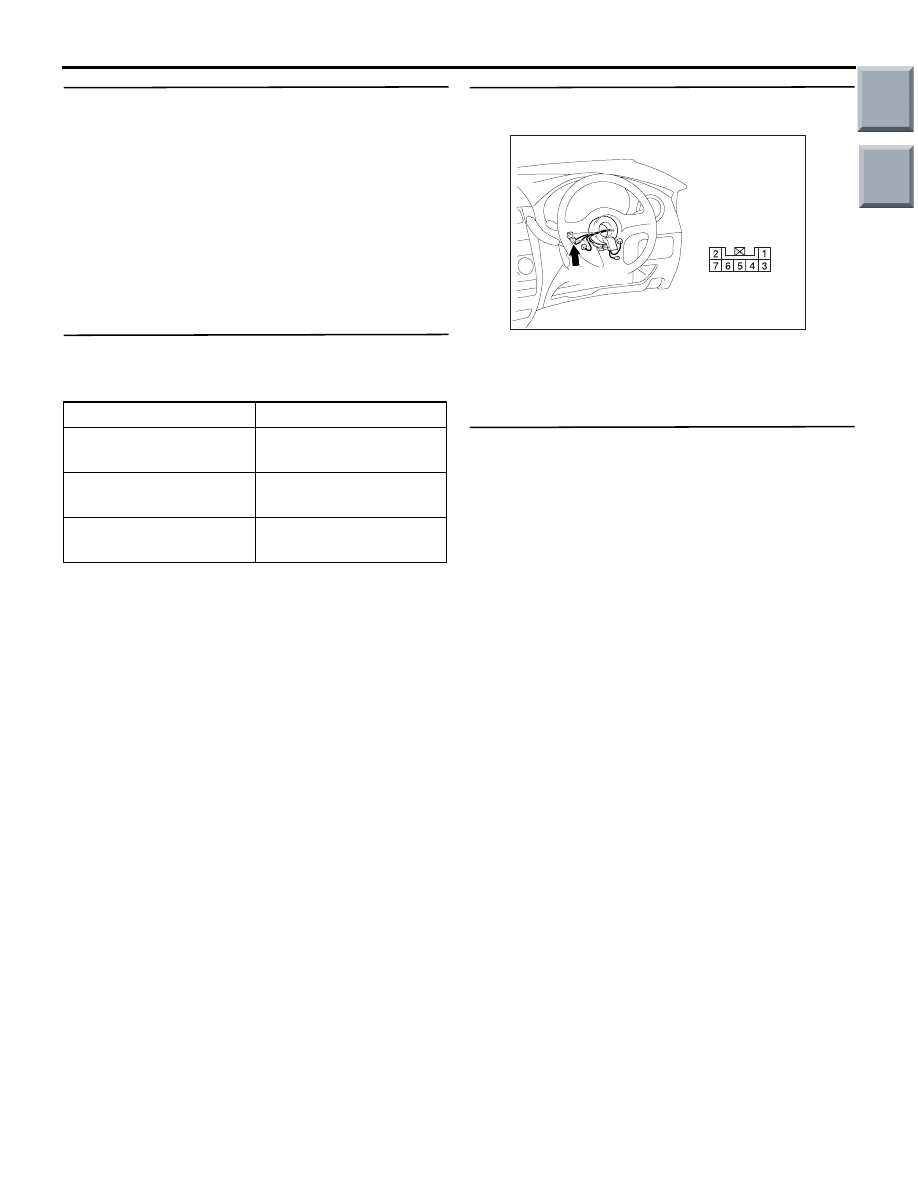
Step 4. Connector check: B-140 key reminder
switch connector.
Q: Is the check result normal?
YES :
Go to Step 5.
NO :
Repair the defective connector.
Step 5. Check the bulb of the ignition key
cylinder illumination lamp.
Check the bulb of the ignition key cylinder illumina-
tion lamp.
Q: Is the check result normal?
YES :
Go to Step 6.
NO :
Replace the bulb of the ignition key cylinder
illumination lamp.
System switch
Check condition
Ignition switch (IG1)
When turned from ACC
to ON
Key reminder switch
When the inserted
ignition key is pulled out
Driver's door switch
When the driver's door is
opened
AC401044
Connector: B-140
AB
Harness side
B-140(B)
Main
Index
Group
TOC