Mitsubishi Colt Ralliart. Manual - part 326


  Index      Mitsubishi     Mitsubishi Colt Ralliart - service repair manual


Search            


Content   ..  324  325  326  327   ..


Mitsubishi Colt Ralliart. Manual - part 326


SYMPTOM PROCEDURES

SMART WIRING SYSTEM (SWS) NOT USING SWS MONITOR

54B-48

INSPECTION PROCEDURE B-2: Door-ajar warning buzzer function does not work.

CAUTION

Whenever the ECU is replaced, ensure that the 
input and output signal circuits are normal.
NOTE: If the CAN bus diagnostics is carried out, the 
door-ajar warning function is triggered.

COMMENTS ON TROUBLE SYMPTOM

The ETACS-ECU operates this function in accord-
ance with the input signals below.

• Ignition switch (IG1)

• All of the door switches

• Vehicle speed signal

If this function does not work normally, these input 
signal circuit(s) or the ETACS-ECU may be defec-
tive. Note that this function can be disabled/enabled 
by the customise function (default setting; enabled). 
In order to change the setting, the SWS monitor is 
required.

POSSIBLE CAUSES

• Malfunction of the CAN bus line

• Malfunction of the door switches

• Malfunction of the ETACS-ECU

• Damaged harness wires and connectors

DIAGNOSTIC PROCEDURE

Step 1. Check the power supply circuit.
When the ignition switch is turned to the LOCK 
(OFF) position, check if the hazard warning lamps 
illuminate.

Q: Is the check result normal?

YES : 

Go to Step 2.

NO : 

Refer to Inspection Procedure A-2 "When 
the ignition switch is at the LOCK (OFF) 
position, the functions do not work normally. 
Check the battery power supply circuit to 
the ETACS-ECU 

P.54B-43

."

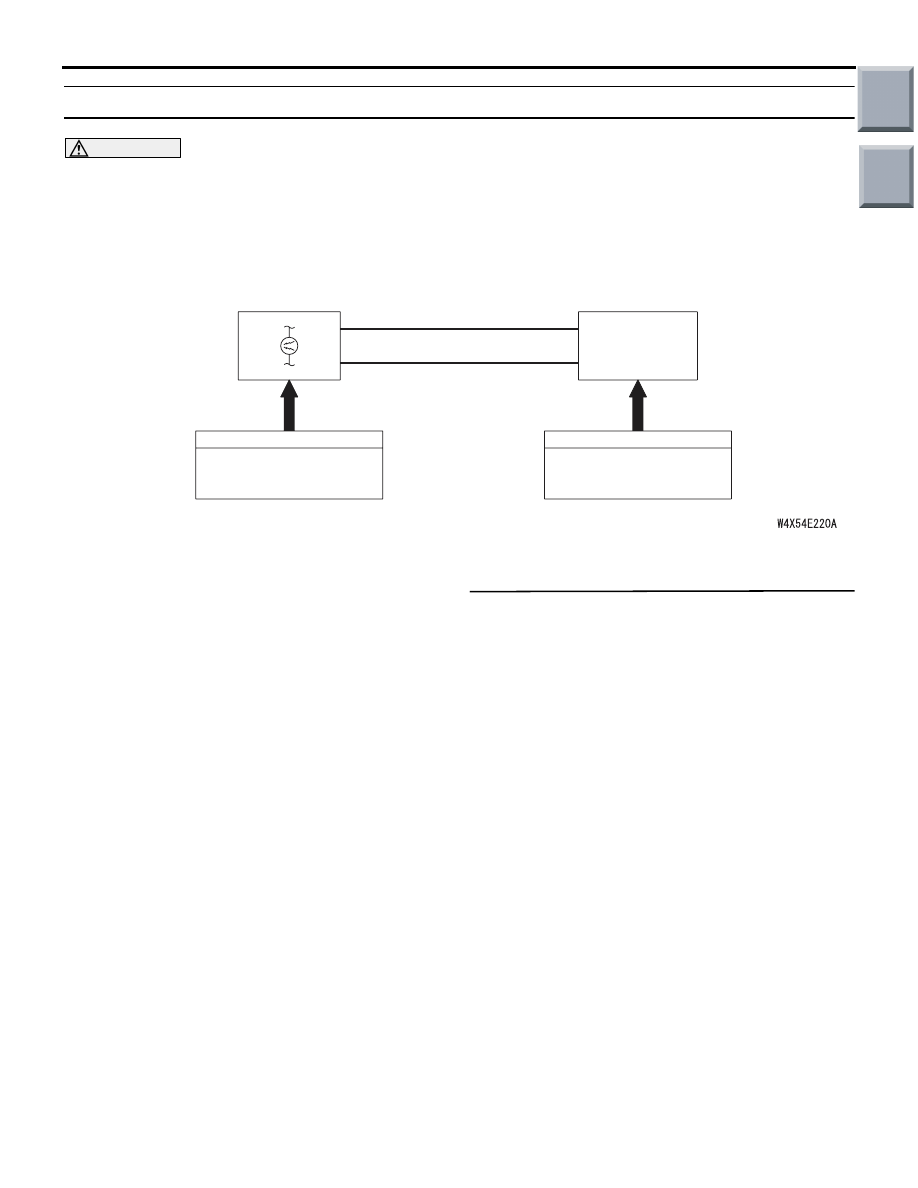
Door-Ajar Warning Buzzer Function

ETACS-
ECU

SPEED SIGNAL

COMBINATION
METER

CAN COMMUNICATION LINE
(CAN_L LINE)

CAN COMMUNICATION LINE
(CAN_H LINE)

INPUT SIGNAL

INPUT SIGNAL

· DOOR SWITCHES
· IGNITION SWITCH (IG1)
· TAILGATE SWITCH

Main

Index

Group

TOC

SYMPTOM PROCEDURES

SMART WIRING SYSTEM (SWS) NOT USING SWS MONITOR

54B-49

Step 2. Pulse check
Check the input signals below, which are related to 
the door-ajar warning buzzer function.

OK: The M.U.T.-III sounds or the voltmeter 
needle fluctuates.

Q: Are the check result normal?

All the signals are received normally. : 

Go to Step 

3.

The ignition switch (IG1) signal is not received. : 

Refer to Inspection Procedure N-2 "The 
ignition switch (IG1) signal is not received 

P.54B-202

."

All the door switch signals are not received. : 

Refer to Inspection Procedure N-10 "All the 
door switch signals are not received 

P.54B-219

."

Step 3. M.U.T.-III CAN bus diagnostics
Use the M.U.T.-III to diagnose the CAN bus lines.

Q: Is the check result normal?

YES : 

Go to Step 4.

NO : 

Repair the CAN bus line (Refer to GROUP 
54D, Diagnosis 

P.54D-13

).

Step 4. M.U.T.-III other system diagnosis code
Check whether the combination meter-related diag-
nosis code is set.

Q: Is the diagnosis code set?

YES : 

Diagnose the combination meter (Refer to 

GROUP 54A 

− Troubleshooting 

P.54A-31

).

NO : 

Go to Step 5.

Step 5. Customize function by using the SWS 
monitor
Use the SWS monitor customise function to confirm 
that "DOOR WARN BUZ" is set to "W.FUNCTION".

CAUTION

The SWS monitor must be used in order to con-
firm and change that setting. Use the SWS moni-
tor to confirm and/or change the customised 
function.

Q: Is the check result normal?

YES : 

Go to Step 6.

NO : 

Use the SWS monitor customise function to 
set "DOOR WARN BUZ" to "W.FUNCTION" 
(Refer to GROUP 54C 

− Customize function 

P.54C-240

).

Step 6. Retest the system.
Check that the door-ajar warning buzzer function 
works normally.

Q: Is the check result normal?

YES : 

The trouble can be an intermittent 

malfunction (Refer to GROUP 00 

− How to 

use Troubleshooting/inspection Service 
Points 

− How to Cope with Intermittent 

Malfunction 

P.00-13

).

NO : 

Replace the ETACS-ECU.

System switch

Check condition

Ignition switch (IG1)

When turned from ACC 
to ON

All of the door switches

A door is opened when 
all the doors are closed

Main

Index

Group

TOC

SYMPTOM PROCEDURES

SMART WIRING SYSTEM (SWS) NOT USING SWS MONITOR

54B-50

INSPECTION PROCEDURE B-3: Turn-signal lamp operation sound function does not work normally.

CAUTION

Whenever the ECU is replaced, ensure that the 
input and output signal circuits are normal.

COMMENTS ON TROUBLE SYMPTOM

The ETACS-ECU operates this function in accord-
ance with the input signals below.

• Turn-signal lamp switch

• Hazard warning lamp switch

If this function does not work normally, these input 
signal circuit(s) or the ETACS-ECU may be defec-
tive. Note that this function can be disabled/enabled 
by the customise function (default setting; disabled). 
In order to change the setting, the SWS monitor is 
required.

POSSIBLE CAUSES

• Malfunction of the column switch

• Malfunction of the ETACS-ECU

• Damaged harness wires and connectors

DIAGNOSTIC PROCEDURE

Step 1. Check that the turn-signal lamps operate.
When the turn-signal lamp switch or the hazard 
warning lamp switch is operated, check that the 
turn-signal lamps flash.

Q: Is the check result normal?

YES : 

Go to Step 2.

NO : 

First, repair the turn-signal lamp(s) (Refer to 
Trouble Symptom Chart 

P.54B-35

).

Step 2. Check the power supply circuit.
When the ignition switch is turned to the LOCK 
(OFF) position, check if the hazard warning lamps 
illuminate.

Q: Is the check result normal?

YES : 

Go to Step 3.

NO : 

Refer to Inspection Procedure A-2 "When 
the ignition switch is at the LOCK (OFF) 
position, the functions do not work normally. 
Check the battery power supply circuit to 
the ETACS-ECU 

P.54B-43

."

Turn-Signal Lamp Operation Sound Function

ETACS-ECU

INPUT SIGNAL

·HAZARD WARNING LAMP SWITCH

·IGNITION SWITCH (IG1)

·TURN-SIGNAL SWITCH

Main

Index

Group

TOC

SYMPTOM PROCEDURES

SMART WIRING SYSTEM (SWS) NOT USING SWS MONITOR

54B-51

Step 3. Pulse check
Check the input signals below, which are related to 
the turn-signal lamp operation sound function.

OK: The M.U.T.-III sounds or the voltmeter 
needle fluctuates.

Q: Are the check result normal?

All the signals are received normally. : 

Go to Step 

4.

The ignition switch (IG1) signal is not received. : 

Refer to Inspection Procedure N-2 "The 
ignition switch (IG1) signal is not received" 

P.54B-202

.

The turn-signal lamp switch (RH) signal is not 
received. : 

Refer to Inspection Procedure N-4 

"The column switch (lighting and turn-signal 
lamp switch) signal is not received" 

P.54B-206

.

The turn-signal lamp switch (LH) signal is not 
received. : 

Refer to Inspection Procedure N-4 

"The column switch (lighting and turn-signal 
lamp switch) signal is not received" 

P.54B-206

.

Step 4. Customize function by using the SWS 
monitor
Use the SWS monitor customise function to confirm 
that "T/SIG.BUZZER" is set to "W.FUNCTION".

CAUTION

The SWS monitor must be used in order to con-
firm and change that setting. Use the SWS moni-
tor to confirm and/or change the customised 
function.

Q: Is the check result normal?

YES : 

Go to Step 5.

NO : 

Use the SWS monitor customise function to 
set "T/SIG.BUZZER" to "W.FUNCTION" 
(Refer to GROUP 54C 

− Customize function 

P.54C-240

).

Step 5. Retest the system.
Check that the turn-signal lamp operation sound 
function works normally.

Q: Is the check result normal?

YES : 

The trouble can be an intermittent 

malfunction (Refer to GROUP 00 

− How to 

use Troubleshooting/inspection Service 
Points 

− How to Cope with Intermittent 

Malfunction 

P.00-13

).

NO : 

Replace the ETACS-ECU.

System switch

Check conditions

Ignition switch (IG1)

When turned from ACC 
to ON

Turn-signal lamp switch 
(RH)

When the turn-signal 
lamp switch (RH) is 
turned from off to on

Turn-signal lamp switch 
(LH)

When the turn-signal 
lamp switch (LH) is 
turned from off to on

Main

Index

Group

TOC


Content   ..  324  325  326  327   ..