Mitsubishi Colt Ralliart. Manual - part 290


  Index      Mitsubishi     Mitsubishi Colt Ralliart - service repair manual


Search            


Content   ..  288  289  290  291   ..


Mitsubishi Colt Ralliart. Manual - part 290


FORWARD CLUTCH

CONTINUOUSLY VARIABLE TRANSMISSION OVERHAUL

23B-33

>>D<< SNAP RING INSTALLATION

AK202445

MB991628

MD998924

AC

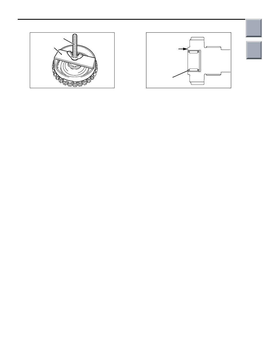
1. Fit the snap ring in the snap ring groove of the 

forward clutch retainer.

2. Press all around the clutch reaction plate using 

the special tools. 

• Spring compressor retainer (MD998924)

• Spring compressor (MB991628)

3. Check whether the clearance between the snap 

ring and clutch reaction plate conforms to the 
standard value.

4. If the clearance deviates from the standard value, 

adjust it by changing the snap ring to a one of an 
appropriate size.

Standard value: 1.2 

 1.4 mm 

>>E<< BEARING INSTALLATION

AK202446

A

Stamped mark 
side

AC

Press fit the bearing until its stamped mark surface 
becomes flush with the surface A shown.

Main

Index

Group

TOC

REVERSE BRAKE

CONTINUOUSLY VARIABLE TRANSMISSION OVERHAUL

23B-34

REVERSE BRAKE

DISASSEMBLY AND REASSEMBLY

M1233210000092

AK102834AD 

1

2

3

4

5

6

7

8

9

10

Apply automatic
transmission fluid
to all moving parts
before installation.

Disassembly steps 

>>

D

<<

1.

Snap ring

>>

C

<<

2.

Brake reaction plate

>>

C

<<

3.

Brake disc

>>

C

<<

4.

Brake plate

5.

Brake pressure plate

<<

A

>>

>>

B

<<

6.

Snap ring

7.

Spring retainer

8.

Return spring

>>

A

<<

9.

Brake piston

10. Brake retainer

DISASSEMBLY SERVICE POINT
<<A>> SNAP RING REMOVAL

AK202448

MD999577

MD998924

AC

To remove the snap ring, compress the return spring 
by holding down the spring retainer using the indi-
cated special tools.

• Spring compressor retainer (MD998924)

• Spring compressor (MD999577)

Main

Index

Group

TOC

REVERSE BRAKE

CONTINUOUSLY VARIABLE TRANSMISSION OVERHAUL

23B-35

REASSEMBLY SERVICE POINTS
>>A<< BRAKE PISTON INSTALLATION

AK102844

Apply blue petrolatum to the indicated portions of the 
brake piston in order to prevent it from being dam-
aged during installation.

>>B<< SNAP RING INSTALLATION

AK202448

MD999577

MD998924

AC

1. Compress the return spring by holding down the 

spring retainer using the special tools.

• Spring compressor retainer (MD998924)

AK102951

AC

A

A

Opening

Spring compressor (MD999577)

CAUTION

Never locate the ends at the positions A shown.
2. Install the snap ring with its ends directed as 

shown in the illustration.

>>C<< BRAKE PLATES/BRAKE 
DISCS/BRAKE REACTION PLATE/BRAKE 
PRESSURE PLATE INSTALLATION

AK202449

Stamped mark side

Brake plate

Brake disc

AC

Brake reaction plate

Round edge

Brake pressure plate

CAUTION

Immerse the brake discs in ATF before assem-
bling them.
Install the brake plates, brake discs, brake reaction 
plate and brake pressure plate, directing their ends 
as shown in the illustration.

>>D<< SNAP RING INSTALLATION

AK202451

MB991628

MD998924

AC

1. Fit the snap ring in the groove formed in the 

reverse brake retainer.

2. Press all around the brake reaction plate using 

the special tools.

• Spring compressor retainer (MD998924)

• Spring compressor (MB991628)

3. Check whether the clearance between the snap 

ring and brake reaction plate conforms to the 
standard value.

4. If the clearance deviates from the standard value, 

adjust it by changing the snap ring to a one of an 
appropriate size.

Standard value: 1.6 

 1.8 mm

Main

Index

Group

TOC

VALVE BODY

CONTINUOUSLY VARIABLE TRANSMISSION OVERHAUL

23B-36

VALVE BODY

DISASSEMBLY AND REASSEMBLY

M1233211000073

CAUTION

• The valve body assembly underwent fluid pressure adjustments at the factory. Do not disturb set-

ting of the adjusting screw.

AK402210

6

50

49

48

47

46

44

43

52

53

55

41

40

42

39

37

36

34

35

30

29

31

32

33

54

51

45

2

1

3

5

4

7

15

16

17 18

19

20

21

25

27

6.0 ± 1.0 N·m

6.0 ± 1.0 N·m

6.0 ± 1.0 N·m

6.0 ± 1.0 N·m

11 ± 1 N·m

6.0 ± 1 N·m

26

28

23

22

24

8

9

10

38

11

14

12

13

AC

Apply automatic
transmission fluid
to all moving parts
before installation.

The shift control solenoid valve must be installed into the original position whenever it has been 
removed. Otherwise the factory-adjusted primary pressure characteristics will be affected.

Disassembly steps 

1.

Manual valve

2.

Detent spring

3.

Inside separating plate

>>

E

<<

4.

Oil strainer

5.

Oil strainer

<<

A

>>

>>

D

<<

6.

Solenoid valve harness

7.

Stopper plate

8.

Stopper plug

9.

Damper clutch control valve

10. Damper clutch control valve spring
11. Stopper plate
12. Stopper plug

13. Line pressure relief valve spring
14. Line pressure relief valve
15. Stopper plate
16. Line pressure relief sleeve
17. Stopper plate
18. Regulator valve sleeve
19. Regulator valve spring
20. Regulator valve
21. Stopper plate
22. Stopper plug
23. Torque converter pressure control 

valve spring

Disassembly steps (Continued)

Main

Index

Group

TOC


Content   ..  288  289  290  291   ..