Mitsubishi Colt Ralliart. Manual - part 273


  Index      Mitsubishi     Mitsubishi Colt Ralliart - service repair manual


Search            


Content   ..  271  272  273  274   ..


Mitsubishi Colt Ralliart. Manual - part 273


HOW TO USE TROUBLESHOOTING/INSPECTION SERVICE POINTS

GENERAL

00-5

HOW TO USE TROUBLESHOOTING/INSPECTION SERVICE 

POINTS

CONTENTS OF TROUBLESHOOTING

M1001013300028

CAUTION

During diagnosis, a diagnosis code associated 
with other system may be set when the ignition 
switch is turned on with connector(s) discon-
nected. On completion, confirm all systems for 
diagnosis code(s). If diagnosis code(s) are set, 
erase them all.
Troubleshooting of electronic control systems for 
which the M.U.T.-III can be used follows the basic 
outline described below. Even in systems for which 
the M.U.T.-III cannot be used, some of these sys-
tems still follow this outline.

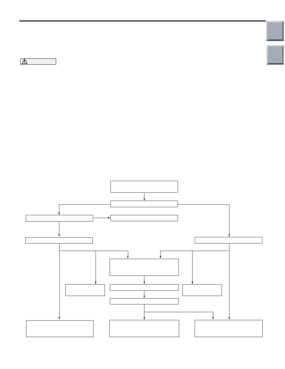
1. STANDARD FLOW OF DIAGNOSIS TROUBLESHOOTING
Troubleshooting sections are based on the diagnostic flow as below. If the diagnostic flow is different from 
that given below, or if additional explanation is required, the details of such differences or additions will also 
be listed.

Diagnosis method

AC505173

Gathering information
from the customer. 

Check trouble symptom.

Reoccurs

Does not reoccur

CAN bus diagnosis chart*

  CAN bus diagnosis*

Read the diagnosis code.

Read the diagnosis code.

After taking note of the 
malfunction code, erase the
diagnosis code memory.

Recheck trouble symptom.

Read the diagnosis codes.

How to treat past 
trouble*

Refer to the INSPECTION CHART
FOR DIAGNOSIS CODES 
(Refer to applicable group).

How to treat past 
trouble*

Refer to the INSPECTION CHART
FOR TROUBLE  SYMPTOMS 
(Refer to applicable group).

INTERMITTENT MALFUNCTIONS

*

Diagnosis code
displayed.
(Current trouble)*

Diagnosis code
displayed.
(Current trouble)*

No diagnosis
code.

No diagnosis
code.

Diagnosis code
displayed.
(Past trouble)*

Diagnosis code
displayed.
(Past trouble)*

No diagnosis code
or communication
with M.U.T.-III not
possible

Diagnosis code
displayed.

OK

NG

2

1

3

3

3

3

4

4

5

Main

Index

Group

TOC

HOW TO USE TROUBLESHOOTING/INSPECTION SERVICE POINTS

GENERAL

00-6

• *

1

: For how to diagnose CAN bus lines, refer to GROUP 54D 

P.54D-7

.

• *

2

: For the CAN bus diagnosis chart, refer to GROUP 54D 

P.54D-13

.

• *

3

: When the M.U.T.-III detects a diagnosis code, its display informs users whether a mechanical problem 

currently exists or whether it existed before. The message for the former state identifies it as a "Active" 
and the message for the latter identifies it as a "Stored".

• *

4

: For how to treat past trouble, refer to 

P.00-13

.

• *

5

: For how to cope with intermittent malfunctions, refer to 

P.00-13

.

2. SYSTEM OPERATION AND SYMPTOM 
VERIFICATION TESTS

If verification of the symptom(s) is difficult, proce-
dures for checking operation and verifying symptoms 
are shown.

3. DIAGNOSIS FUNCTION

Details which are different from those in the "Diagno-
sis Function 

P.00-7

" section are described.

4. DIAGNOSIS CODE CHART

Diagnostic trouble codes and diagnostic items are 
shown.

5. DIAGNOSIS CODE PROCEDURES

Indicates the inspection procedures corresponding to 
each diagnosis code (Refer to How to Use Inspection 
Procedures 

P.00-8

).

6. TROUBLE SYMPTOM CHART

If there are trouble symptoms even though the 
M.U.T.-III does not find any diagnosis codes, Inspec-
tion procedures for each trouble symptom will be 
found by means of this chart.

7. SYMPTOM PROCEDURES

Indicates the inspection procedures corresponding to 
each symptoms classified in the Symptom Chart 
(Refer to How to Use Inspection Procedures 

P.00-8

).

8. SERVICE DATA REFERENCE TABLE

Inspection items and normal judgment values have 
been provided in this chart as reference information.

9. ACTUATOR TEST TABLE

The Actuator Test item numbers, inspection items, 
and judgment values have been provided in this 
chart as reference information.

10. CHECK AT ECU TERMINALS

Terminal numbers for the ECU connectors, inspec-
tion items, and judgment values have been provided 
in this chart as reference information.

11. INSPECTION PROCEDURE BY USING 
AN OSCILLOSCOPE

When there are inspection procedures using an 
oscilloscope, these are described here.

Main

Index

Group

TOC

HOW TO USE TROUBLESHOOTING/INSPECTION SERVICE POINTS

GENERAL

00-7

DIAGNOSIS FUNCTION

M1001013400025

HOW TO READ DIAGNOSIS CODE 

CAUTION

Before connecting or disconnecting the 
M.U.T.-III, turn the ignition switch to the "LOCK" 
(OFF) position.

AC206895

AC

Diagnosis

connector

MB991827

MB991824 

MB991910

Connect the M.U.T.-III to the 16-pin diagnosis con-

nector, and read the diagnosis code.
NOTE: . For details on how to use the M.U.T.-III, 

refer to the "M.U.T.-III operation manual."
1. Ensure that the ignition switch is at the "LOCK" 

(OFF).

2. Start up the personal computer.
3. Connect M.U.T.-III USB cable (MB991827) to 

special tool Vehicle Communication Interface 

(V.C.I.) (MB991824) and the personal computer.

4. Connect M.U.T.-III main harness A (MB991910) to 

the V.C.I.

5. Connect the M.U.T.-III main harness A to the 

diagnosis connector.

6. Turn the V.C.I. power switch to the "ON" position.

NOTE: . When the V.C.I. is energized, the V.C.I. 

indicator lamp will be illuminated in a green col-

our.

7. Start the M.U.T.-III system on the personal 

computer and turn the ignition switch to the "ON" 

position.

8. Read the diagnosis code.
9. Disconnecting the M.U.T.-III is the reverse of the 

connecting sequence, making sure that the 

ignition switch is at the "LOCK" (OFF).

ERASING DIAGNOSIS CODE

CAUTION

Before connecting or disconnecting the 
M.U.T.-III, turn the ignition switch to the "LOCK" 
(OFF) position.

AC206895

AC

Diagnosis

connector

MB991827

MB991824 

MB991910

Connect the M.U.T.-III to the diagnosis connector, 
and erase the diagnosis code. The procedure is the 
same as "How to Read Diagnosis Code."

INPUT SIGNAL CHECK (WHEN USING A 
VOLTMETER) <SWS>

AC310121

MB991529

AB

1. Use special tool diagnosis code check harness 

(MB991529) to connect the ETACS terminal 
(terminal 9) and the earth terminals (terminals 4 
and 5) of the diagnosis connector to the voltage 
meter.

2. If the needle of the voltage meter flickers once 

when each switch is operated (ON/OFF), the input 
signal for that switch circuit system is normal.

Main

Index

Group

TOC

HOW TO USE TROUBLESHOOTING/INSPECTION SERVICE POINTS

GENERAL

00-8

HOW TO USE THE INSPECTION 
PROCEDURES

M1001013500367

The causes of many of the problems occurring in electric circuitry are generally the connectors, components, 
the ECU, the wiring harnesses between connectors, in that order. These inspection procedures follow this 
order. They first try to discover a problem with a connector or a defective component.

AC301964 AC

 Relevant circuit(s) of the component which
 the Code No. indicates are described.

Grey

Main

Index

Group

TOC


Content   ..  271  272  273  274   ..