Mitsubishi Colt Ralliart. Manual - part 238
TROUBLESHOOTING
ANTI-SKID BRAKING SYSTEM (ABS)
35B-44
Code No.C1276: Valve relay system
OPERATION
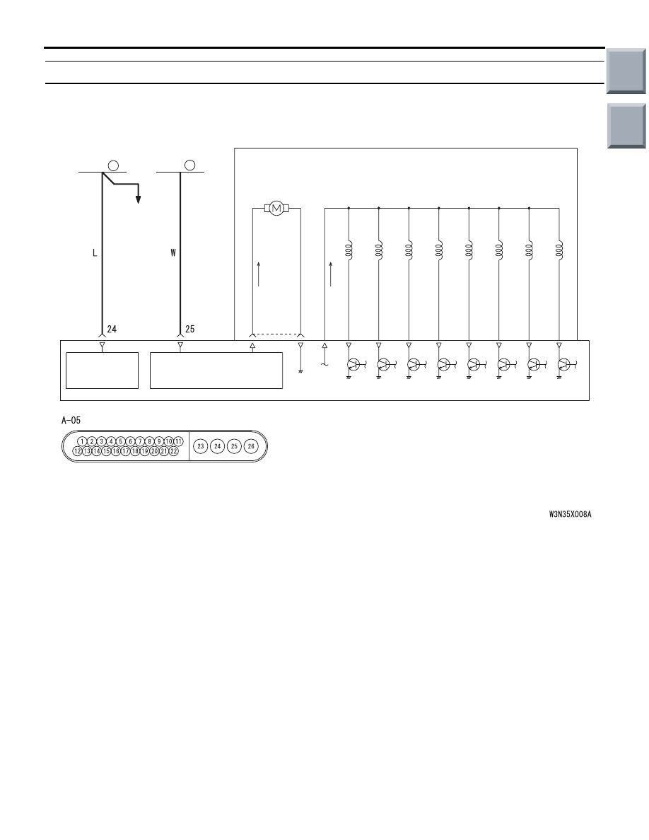
• The ABS-ECU contains the power supply circuit
(terminal No.24) for the solenoid valve. The sole-
noid valve is energised by the valve relay, which
is incorporated in the ABS-ECU.
• The valve relay, which is incorporated in the
ABS-ECU, is always energising the solenoid
valve unless the initial check is in progress when
the ignition switch is turned on, or the recurrent
system check is in progress.
DIAGNOSIS CODE SET CONDITIONS
These diagnosis codes will be set under the cases
below.
• The ABS-ECU monitors the power supply voltage
to the solenoid valve. If the voltage is lower than
the predetermined value, the ECU sets this diag-
nosis code as a failure in the valve relay circuit.
PROBABLE CAUSES
The most likely causes for these diagnosis codes to
set are:
• Damaged wiring harness or connector
• Malfunction of the hydraulic unit (integrated with
ABS-ECU)
ABS-ECU
SOLENOID
VALVE POWER
SOURCE
MOTOR POWER SOURCE
MOTOR
SOLENOID VALVE
HYDRAULIC UNIT
FUSIBLE
LINK
FUSIBLE
LINK
CHARGING
SYSTEM
3
5
Wire colour code
B : Black LG : Light green G : Green L : Blue W : White Y : Yellow SB : Sky blue
BR : Brown O : Orange GR : Gray R : Red P : Pink V : Violet
Hydraulic Unit (Motor and Solenoid Valve) Circuit
Main
Index
Group
TOC