Mitsubishi Colt Ralliart. Manual - part 231


  Index      Mitsubishi     Mitsubishi Colt Ralliart - service repair manual


Search            


Content   ..  229  230  231  232   ..


Mitsubishi Colt Ralliart. Manual - part 231


TROUBLESHOOTING

ANTI-SKID BRAKING SYSTEM (ABS)

35B-16

DIAGNOSIS PROCEDURE

STEP 1. Connector check: A-06 front left wheel 
speed sensor connector

Q: Is the check result normal?

YES : 

Go to Step 2.

NO : 

Repair the defective connector.

STEP 2. Remove the front left wheel speed 
sensor and check it.
Refer to 

P.35B-81

.

Q: Is the check result normal?

YES : 

Go to Step 3.

NO : 

Replace the front left wheel speed sensor 
(Refer to 

P.35B-80

).

STEP 3. Check the front left wheel speed sensor 
connector A-06.

Check the connectors, for loose, corroded or dam-
aged terminals, or terminals pushed back in the con-
nector.

Q: Is the check result normal?

YES : 

Go to Step 4.

NO : 

Repair or replace the damaged 
component(s). Refer to GROUP 00, How to 
Use Troubleshooting/Inspection Service 
Points 

− Connector Inspection Service 

Points 

P.00-11

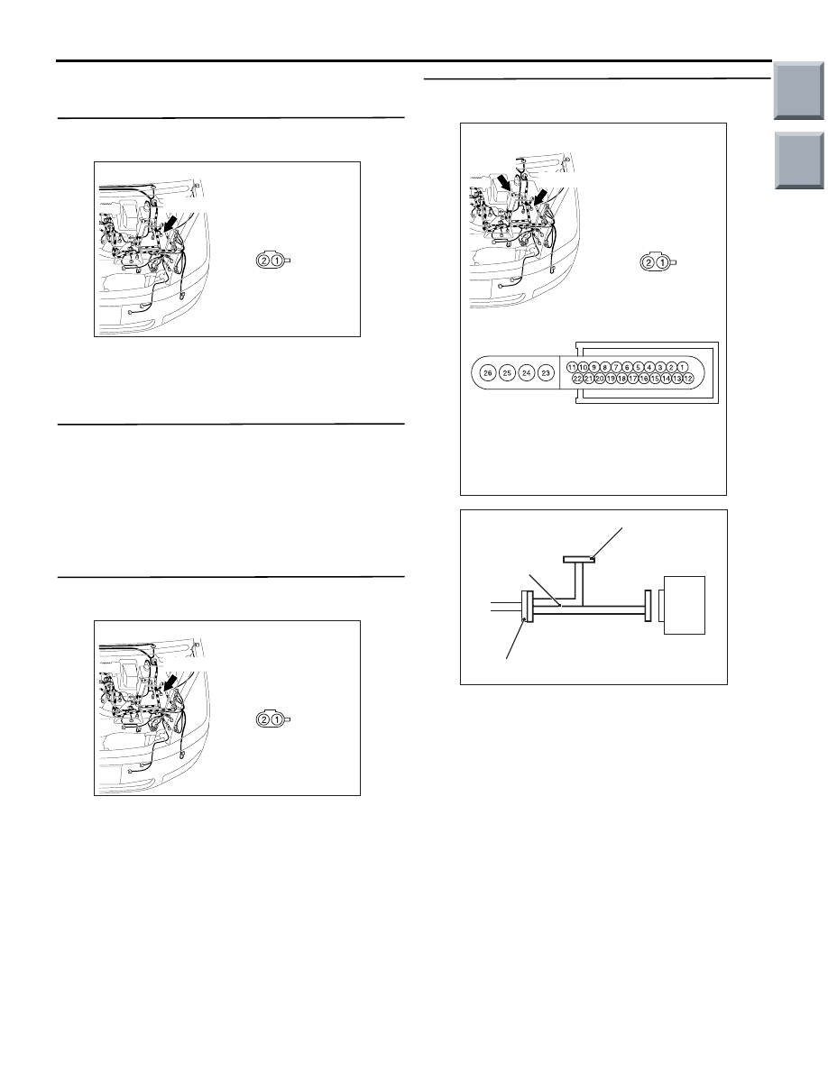
STEP 4. Check the continuity (short to earth) at 
ABS-ECU connector A-05.

(1) Disconnect the front left wheel speed sensor 

connector A-06 and ABS-ECU connector A-05, 
and connect special tool ABS Check Harness 
(MB991951) to the wiring harness-side 
connector.
NOTE: Do not connect special tool ABS Check 
Harness (MB991951) to the ABS-ECU.

AC313862AE

Connector: A-06

Harness side

A-06(B)

AC313862AE

Connector: A-06

Harness side

A-06(B)

AC313863AC

Connectors: A-05, A-06

Harness side

A-05

A-06(B)

A-05(B)

Harness side

A-06

AC314249AB

ABS-ECU

MB991951

Check connector

A-05 Harness connector

Main

Index

Group

TOC

TROUBLESHOOTING

ANTI-SKID BRAKING SYSTEM (ABS)

35B-17

(2) Continuity between ABS-ECU connector A-05 

terminal 11 and body earth

OK: No continuity

(3) Continuity between ABS-ECU connector A-05 

terminal 22 and body earth

OK: No continuity

Q: Is the check result normal?

YES : 

Go to Step 5.

NO : 

Repair the wiring harness between 
ABS-ECU connector A-05 and front left 
wheel speed sensor connector A-06.

STEP 5. Resistance measurement at ABS-ECU 
connector A-05.

(1) Disconnect the front left wheel speed sensor 

connector A-06 and ABS-ECU connector A-05, 
and connect special tool ABS Check Harness 
(MB991951) to the wiring harness-side 
connector.
NOTE: Do not connect special tool ABS Check 
Harness (MB991951) to the ABS-ECU.

AC313972 BI

Connector A-05
 (Harness side)

AC313972BJ

Connector A-05
 (Harness side)

AC313863AC

Connectors: A-05, A-06

Harness side

A-05

A-06(B)

A-05(B)

Harness side

A-06

AC314249AB

ABS-ECU

MB991951

Check connector

A-05 Harness connector

Main

Index

Group

TOC

TROUBLESHOOTING

ANTI-SKID BRAKING SYSTEM (ABS)

35B-18

(2) Resistance between ABS-ECU connector A-05 

terminal 11 and front left wheel speed sensor 
A-06 terminal 1

OK: 10 

 or less

(3) Resistance between ABS-ECU connector A-05 

terminal 22 and front left wheel speed sensor 
A-06 terminal 2

OK: 10 

 or less

Q: Is the check result normal?

YES : 

Go to Step 6.

NO : 

Repair the wiring harness between 
ABS-ECU connector A-05 and front left 
wheel speed sensor connector A-06.

STEP 6. Check whether the diagnosis code is 
reset.

CAUTION

Before connecting or disconnecting the 
M.U.T.-III, turn the ignition switch to the "LOCK" 
(OFF) position.
Check again if the diagnosis code is set.
(1) Turn the ignition switch to the "ON" position.
(2) Erase the diagnosis code.
(3) Turn the ignition switch to the "LOCK" (OFF) 

position.

(4) Turn the ignition switch to the "ON" position.
(5) Check if the diagnosis code is set.
(6) Turn the ignition switch to the "LOCK" (OFF) 

position.

(7) Disconnect M.U.T.-III.

Q: Is code No.C1205 set?

YES : 

Replace the hydraulic unit (integrated with 

ABS-ECU) (Refer to 

P.35B-78

).

NO : 

The malfunction is intermittent. Refer to 
GROUP 00, How to Use 
Troubleshooting/Inspection Service Points 

− 

How to Cope with Intermittent Malfunction 

P.00-13

.

AC314250

Connector A-06
 (Harness side)

AD

MB991951

Check 
connector

ABS-ECU

A-05 Harness connector

AC314250

Connector A-06
 (Harness side)

AE

MB991951

Check 
connector

ABS-ECU

A-05 Harness connector

AC206895

AC

Diagnosis

connector

MB991827

MB991824 

MB991910

Main

Index

Group

TOC

TROUBLESHOOTING

ANTI-SKID BRAKING SYSTEM (ABS)

35B-19

Code No.C1206: Wheel speed sensor (FL) system (sensor output failure)

OPERATION

The wheel speed sensor is a pulse generator. It con-
sists of encoder (a plate on which north and south 
pole sides of the magnets are arranged alternately) 
for detecting wheel speed which rotates at the same 
speed as the road wheels. This sensor sends fre-
quency pulse signals in proportion to wheel speed.
The pulse signals, which the wheel speed sensor 
creates, are sent to the ABS-ECU. The ABS-ECU 
uses the frequency of the pulse signals to determine 
the wheel speed.

DIAGNOSIS CODE SET CONDITIONS

The ABS-ECU monitors the signals from the wheel 
speed sensors during driving. If the ECU detects 
malfunctions below, it sets the diagnosis code.

• Missing of wheel speed sensor signals

• When an abnormal wheel speed sensor signal is 

received

• When one of the wheel speed sensor signals 

(from the front, rear, right and left wheels) is sig-
nificantly different from the others

PROBABLE CAUSES

• Improperly installed wheel speed sensor

• Presence of dirt or other foreign particles on the 

encoder of the wheel speed sensor

• Deformed encoder of the wheel speed sensor

• Excessive gap between the wheel speed sensor 

and its encoder

• Damaged wiring harness or connector

• Malfunction of the wheel speed sensor

• Malfunction of the hydraulic unit (integrated with 

ABS-ECU)

FRONT WHEEL SPEED SENSOR

(LH)

(RH)

(LH)

(RH)

ABS-ECU

REAR WHEEL SPEED SENSOR

Wire colour code
B : Black     LG : Light green     G : Green     L : Blue     W : White     Y : Yellow     SB : Sky blue
BR : Brown     O : Orange     GR : Gray     R : Red     P : Pink     V : Violet

 Wheel Speed Sensor Circuit

Main

Index

Group

TOC


Content   ..  229  230  231  232   ..