Mitsubishi Colt Ralliart. Manual - part 196
TROUBLESHOOTING <CVT>
CVT
23A-127
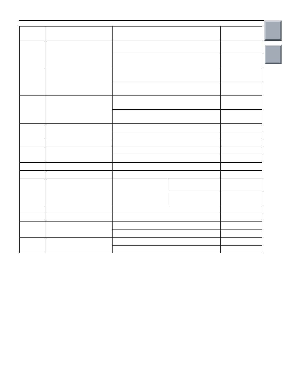
61
Inhibitor switch: Ds
• Ignition switch: ON
• Selector lever position: Ds
System voltage
• Ignition switch: ON
• Selector lever position: Other than above
1 V or less
62
Inhibitor switch: D
• Ignition switch: ON
• Selector lever position: D
System voltage
• Ignition switch: ON
• Selector lever position: Other than above
1 V or less
63
Inhibitor switch: N
• Ignition switch: ON
• Selector lever position: N
System voltage
• Ignition switch: ON
• Selector lever position: Other than above
1 V or less
71
Solenoid valve power
supply
Ignition switch: LOCK (OFF) position
1 V or less
Ignition switch: ON
System voltage
72
Earth
Always
1 V or less
73
Solenoid valve power
supply
Ignition switch: LOCK (OFF) position
1 V or less
Ignition switch: ON
System voltage
74
Earth
Always
1 V or less
82
Back-up power supply
Always
System voltage
83
APS signal
Ignition switch: ON
Accelerator pedal:
Released
0.8
− 1.2 V
Accelerator pedal:
Depressed
4 V or more
84
APS earth
Always
0.5 V or less
85
APS power supply
Ignition switch: ON
4.9
− 5.1 V
124
CVT control relay
Ignition switch: LOCK (OFF) position
System voltage
Ignition switch: ON
1 V or less
128
Stoplamp switch
Brake pedal: Depressed
System voltage
Brake pedal: Released
1 V or less
Terminal
No.
Check item
Inspection condition
Standard value
Main
Index
Group
TOC