Mitsubishi Colt Ralliart. Manual - part 191
TROUBLESHOOTING <CVT>
CVT
23A-107
STEP 2. Check the CVT control relay.
Refer to
Q: Is the check result normal?
YES :
Go to Step 3.
NO :
Replace the CVT control relay.
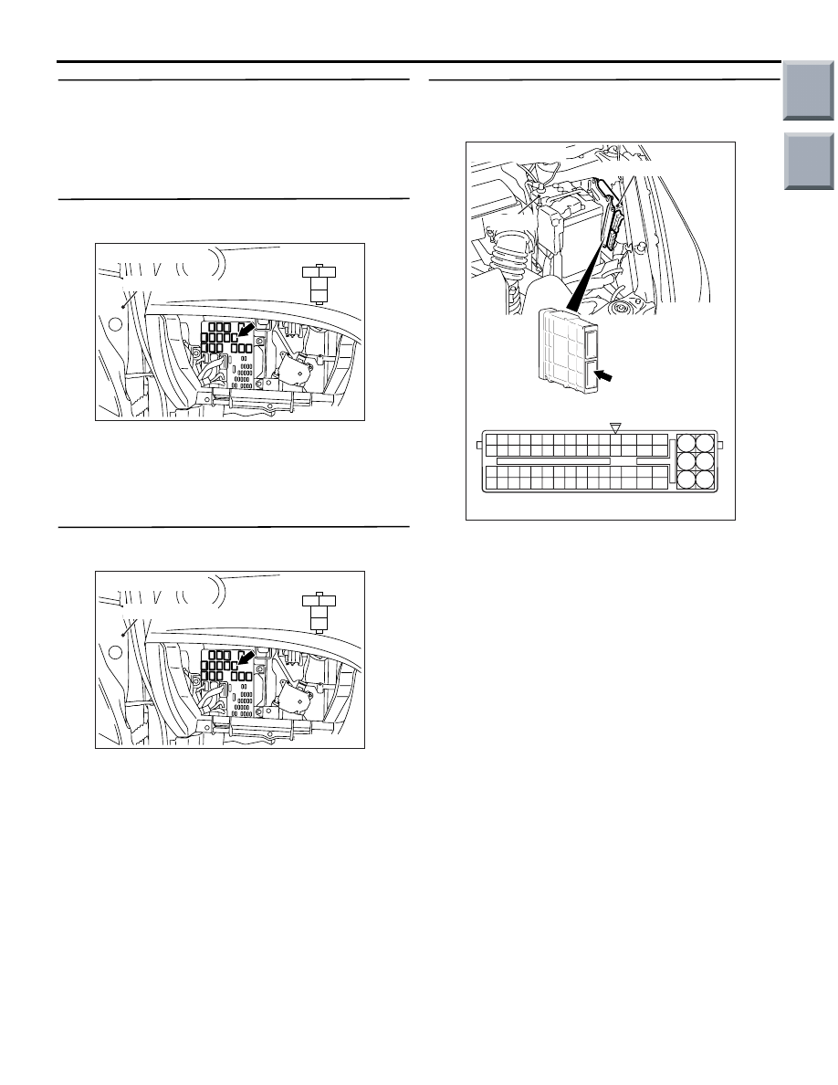
STEP 3. Connector check: B-118 CVT control
relay connector.
AC208716
AB
1
2
3
4
J/B side connector
Front door <LH>
Connector: B-118
Check for the contact with terminals.
Q: Is the check result normal?
YES :
Go to Step 4.
NO :
Repair the defective connector.
STEP 4. Measure the voltage at CVT control relay
connector B-118.
AC208716
AB
1
2
3
4
J/B side connector
Front door <LH>
Connector: B-118
Disconnect the CVT control relay, and measure the
voltage between terminal No.1, 3 and earth at the
J/B side.
OK: System voltage
Q: Is the check result normal?
YES :
Go to Step 5.
NO :
Go to Step 13.
STEP 5. Measure the voltage at engine-CVT-ECU
connector A-08.
(1) Install the CVT control relay.
AC403088AI
A-08
Connector: A-08
Engine-CVT-ECU
Battery
77
78
79
80
81
82
83
84
92
93
94
95
96
97
98
99
85
86
87
88
89
90
91
100
101
102
103
104
105
106
115
116
117
118
119
120
121
107
108
109
110
111
112
113
114
130
131
132
133
134
135
136
122
123
124
125
126
127
128
129
72 71
74 73
76 75
R
A-08 Check connector (special tool)
(GR)
(2) Disconnect the engine-CVT-ECU connector, and
connect the special tool Power plant ECU check
harness (MB991987).
(3) Use the special tool Check connector to measure
the voltage between engine-CVT-ECU connector
A-08 terminal No.124 and earth.
OK:
Turn the ignition switch to the OFF posi-
tion: System voltage
Turn the ignition switch to the ON position:
1 V or less
Q: Is the check result normal?
YES :
Go to Step 9.
NO :
Go to Step 6.
Main
Index
Group
TOC