Mitsubishi Colt Ralliart. Manual - part 120


  Index      Mitsubishi     Mitsubishi Colt Ralliart - service repair manual


Search            


Content   ..  118  119  120  121   ..


Mitsubishi Colt Ralliart. Manual - part 120


CHARGING SYSTEM

ENGINE ELECTRICAL

16-14

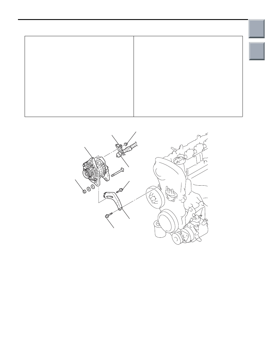
REMOVAL AND INSTALLATION <4G1>

M1161001401648

Pre-removal Operation
• Engine Cover Removal (Refer to GROUP 11C, Camshaft 

and Valve Stem Seal 

P.11C-20

).

• Side Under Cover Panel (RH) Removal

• A/C Compressor Drive Belt and Alternator Drive Belt 

Removal (Refer to GROUP 11C, Crankshaft Pulley 

P.11C-17

).

• Exhaust Centre Pipe and Exhaust Front Pipe Removal 

(Refer to GROUP 15, Exhaust Pipe and Main Muffler 

P.15-21

).

• Front Suspension Axle Side Plate Removal (Refer to 

GROUP 32, Front Axle Crossmember 

P.32-17

).

• Inlet Manifold Stay Removal (Refer to GROUP 15, Inlet 

Manifold 

P.15-12

).

Post-installation Operation
• Inlet Manifold Stay Installation (Refer to GROUP 15, Inlet 

Manifold 

P.15-12

).

• Front Suspension Axle Side Plate Installation (Refer to 

GROUP 32, Front Axle Crossmember 

P.32-17

).

• Exhaust Centre Pipe and Exhaust Front Pipe Installation 

(Refer to GROUP 15, Exhaust Pipe and Main Muffler 

P.15-21

).

• A/C Compressor Drive Belt and Alternator Drive Belt 

Installation (Refer to GROUP 11C, Crankshaft Pulley 

P.11C-17

).

• Drive Belt Tension Check and Adjustment (Refer to 

GROUP 11C, On-Vehicle Service 

− Drive Belt Tension 

Check and Adjustment 

P.11C-8

).

• Side Under Cover Panel (RH) Installation

• Engine Cover Installation (Refer to GROUP 11C, Cam-

shaft and Valve Stem Seal 

P.11C-20

).

AC402110

23 ± 2 N·m

1

3

4

2

AB

24 ± 3 N·m

44 ± 10 N·m

14 ± 3 N·m

Removal steps 

1.

Alternator connector

2.

Alternator terminal

<<

A

>>

3.

Alternator assembly

>>

A

<<

4.

Alternator brace

Removal steps (Continued)

Main

Index

Group

TOC

CHARGING SYSTEM

ENGINE ELECTRICAL

16-15

REMOVAL SERVICE POINT
<<A>> ALTERNATOR ASSEMBLY 
REMOVAL

AC207085AD

Alternator 
assembly

Front axle No.1
crossmember

Front floor

Remove the alternator assembly from between the 
front floor and the front axle No.1 crossmember.

INSTALLATION SERVICE POINT
>>A<< ALTERNATOR BRACE INSTALLA-
TION

AC403625AB

Nut

Install the alternator brace nut so that it is in the 
direction shown.

Main

Index

Group

TOC

CHARGING SYSTEM

ENGINE ELECTRICAL

16-16

 DISASSEMBLY AND ASSEMBLY

M1161001600274

AK201192 AD

1

2

7

6

5

3

4

8

9

10

12

13

14

11

4.4 ± 1.0  N·m

3.9 ± 1.0 N·m

3.9 ± 1.0 N·m

120 ± 20 N·m

16 ± 3 N·m

Disassembly steps 

<<

A

>>

1. Front bracket assembly

<<

B

>>

2. Alternator pulley

>>

B

<< 3. Rotor

4. Rear bearing
5. Bearing retainer
6. Front bearing
7. Front bracket

<<

C

>>

8. Stator
9. Plate

<<

C

>> >>

A

<< 10. Regulator assembly

11. Brush
12. Rubber packing
13. Rectifier
14. Rear bracket

Disassembly steps (Continued)

Main

Index

Group

TOC

CHARGING SYSTEM

ENGINE ELECTRICAL

16-17

DISASSEMBLY SERVICE POINTS
<<A>> FRONT BRACKET ASSEMBLY 
REMOVAL

AK202718

CAUTION

Do not insert the screwdriver blades too deep. 
Doing so could damage the stator coil.
Insert the blades of screwdrivers between the front 
bracket assembly and stator core, and pry and sepa-
rate them with the screwdrivers.

<<B>> ALTERNATOR PULLEY REMOVAL

AK202714

CAUTION

Perform operation carefully not to damage the 
rotor.
Clamp the rotor in a vise with the pulley facing up to 
remove the pulley.

<<C>> STATOR / REGULATOR 
ASSEMBLY REMOVAL

AK202778

Solder

Solder

Rectifier 
assembly

AB

CAUTION

• Use a 180  250 W soldering iron, and finish 

unsoldering within four seconds. Diodes will 
be damaged by heat if unsoldering time is too 
long.

• Avoid applying undue force to the diode 

leads.

1. Unsolder the stator leads from the main diode of 

the rectifier assembly when the stator is removed.

2. When removing the rectifier assembly from the 

regulator assembly, undo the soldered points on 
the rectifier assembly.

REASSEMBLY SERVICE POINTS
>>A<< REGULATOR ASSEMBLY INSTAL-
LATION

AK202779

Wire

AB

AK202830

Rear bracket

Brush

Wire

AB

After installing the regulator assembly, insert a piece 
of wire through the hole in the rear bracket while 
pressing the brush to keep the brush against move-
ment.
NOTE: Holding the brush with the wire facilities 
installation of the rotor.

Main

Index

Group

TOC


Content   ..  118  119  120  121   ..