Mitsubishi Colt Ralliart. Manual - part 65


  Index      Mitsubishi     Mitsubishi Colt Ralliart - service repair manual


Search            


Content   ..  63  64  65  66   ..


Mitsubishi Colt Ralliart. Manual - part 65


TROUBLESHOOTING

MULTIPORT FUEL INJECTION (MPI) <4A9>

13A-214

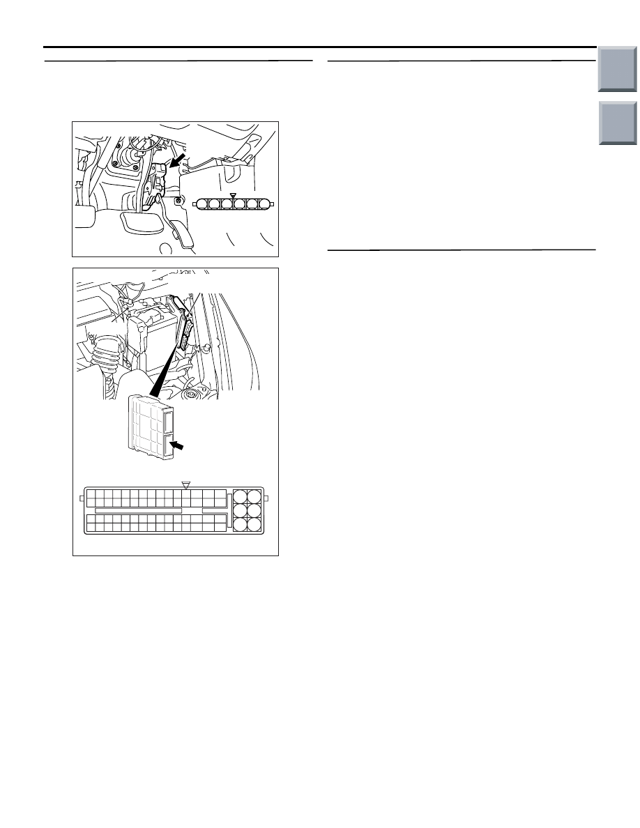
STEP 5. Check harness between B-26 (terminal 
No. 5) accelerator pedal position sensor 
connector and A-08 (terminal No. 87) engine-ECU 
connector or engine-CVT-ECU connector.

• Check earthing line for open circuit and damage.

Q: Is the check result normal?

YES : 

Go to Step 6 .

NO : 

Repair the damaged harness wire.

STEP 6. M.U.T.-III data list

• Refer to Data List Reference Table 

P.13A-331

.

a. Item 77: Accelerator pedal position sensor 

(sub)

Q: Is the check result normal?

YES : 

Intermittent malfunction (Refer to GROUP 

00 

− How to Use 

Troubleshooting/Inspection Service Points 

− 

How to Cope with Intermittent Malfunctions 

P.00-13

).

NO : 

Replace the engine-ECU <M/T> or 
engine-CVT-ECU <CVT>.

STEP 7. Replace the accelerator pedal assembly.

• After replacing the accelerator pedal assembly, 

re-check the trouble symptoms.

Q: Is the check result normal?

YES : 

Check end.

NO : 

Replace the engine-ECU <M/T> or 
engine-CVT-ECU <CVT>.

AK203205

1

6 5 4 3 2

AD

Connector: B-26

B-26 (B)

B-26 Harness side
connector

AK402725

77

78

79

80

81

82

83

84

92

93

94

95

96

97

98

99

85

86

87

88

89

90

91

100

101

102

103

104

105

106

115

116

117

118

119

120

121

107

108

109

110

111

112

113

114

130

131

132

133

134

135

136

122

123

124

125

126

127

128

129

72 71

74 73

76 75

R

AG

A-08

Connector: 

A-08

Harness side connector

Battery

Engine-ECU <M/T> or
engine-CVT-ECU <CVT>

Main

Index

Group

TOC

TROUBLESHOOTING

MULTIPORT FUEL INJECTION (MPI) <4A9>

13A-215

Code No. P2135: Throttle Position Sensor (Main and Sub) Range/Performance Problem

OPERATION

• Refer to Code No. P0122: Throttle Position Sen-

sor (main) Circuit Low Input 

P.13A-50

.

• Refer to Code No. P0222: Throttle Position Sen-

sor (sub) Circuit Low Input 

P.13A-109

.

FUNCTION

• The engine-ECU <M/T> or engine-CVT-ECU 

<CVT> checks the throttle position sensor output 
signal characteristics for abnormal conditions.

TROUBLE JUDGMENT

Check Conditions

• Ignition switch is in "ON" position.

• Throttle position sensor (main/sub) is normal.

• Throttle position sensor (main) output voltage is 

0.2 V or more and 4.8 V or less <M/T>.

• Throttle position sensor (sub) output voltage is 

0.2 V or more and 4.8 V or less <M/T>.

• Throttle position sensor (main) output voltage is 

0.2 

− 2.5 V <CVT>.

• The output voltage value of the sub throttle posi-

tion sensor subtracted from 5 V equals 0.2 

− 2.5 

V <CVT>.

• The fully closed learning of the throttle valve is 

completed <CVT>.

• Battery positive voltage is more than 8.3 V 

<CVT>.

Judgment Criteria

• Total output voltage sum of the throttle position 

sensor (main) and throttle position sensor (sub) is 
4.5 V or more and 5.5 V or less <M/T>.

• Change of throttle position sensor (sub) output 

voltage per 25 milliseconds is lower than 0.1 V 
<CVT>.

• The output voltage sum of the throttle position 

sensor (main) and the throttle position sensor 
(sub) deviates from the specified range <CVT>.

PROBABLE CAUSES

• Failed throttle position sensor

• Open/short circuit in throttle position sensor cir-

cuit or loose connector contact

• Failed engine-ECU <M/T> or engine-CVT-ECU 

<CVT>

DIAGNOSIS PROCEDURE

STEP 1. Connector check: A-114 engine-ECU 
connector or engine-CVT-ECU connector and 
A-107 electronic-controlled throttle valve 
connector

Q: Is the check result normal?

YES : 

Go to Step 2 .

NO : 

Repair or replace the connector.

AK402745

6

4

2

5

3

1

9

7

8

10

11

12

13

14

15

16

17

18

19

20

21

22

23

24

25

26

27

28

29

30

31

32

33

34

35

36

37

38

39

40

41

42

43

44

45

46

47

48

49

50

51

52

53

54

55

56

57

58

59

60

61

62

63

64

65

66

L

AD

A-114

Connector: 

A-114

Harness side connector

Engine-ECU <M/T> or
engine-CVT-ECU <CVT>

Battery

AK402006

1

6 5 4 3 2

AC

A-107 (B)

Connector: A-107

A-107 Harness side
connector

Main

Index

Group

TOC

TROUBLESHOOTING

MULTIPORT FUEL INJECTION (MPI) <4A9>

13A-216

STEP 2. Check harness between A-107 (terminal 
No. 6) electronic-controlled throttle valve 
connector and A-114 (terminal No. 15) 
engine-ECU connector or engine-CVT-ECU 
connector.

• Check output line for short circuit and damage.

Q: Is the check result normal?

YES : 

Go to Step 3 .

NO : 

Repair the damaged harness wire.

STEP 3. Check harness between A-107 (terminal 
No. 4) electronic-controlled throttle valve 
connector and A-114 (terminal No. 16) 
engine-ECU connector or engine-CVT-ECU 
connector.

• Check output line for short circuit.

Q: Is the check result normal?

YES : 

Go to Step 4 .

NO : 

Repair the damaged harness wire.

STEP 4. Replace throttle body assembly.

• After throttle body assembly is replaced, re-check 

for trouble symptom.

Q: Does trouble system persist?

YES : 

Replace engine-ECU <M/T> or 

engine-CVT-ECU <CVT>.

NO : 

Check end.

AK402006

1

6 5 4 3 2

AC

A-107 (B)

Connector: A-107

A-107 Harness side
connector

AK402745

6

4

2

5

3

1

9

7

8

10

11

12

13

14

15

16

17

18

19

20

21

22

23

24

25

26

27

28

29

30

31

32

33

34

35

36

37

38

39

40

41

42

43

44

45

46

47

48

49

50

51

52

53

54

55

56

57

58

59

60

61

62

63

64

65

66

L

AD

A-114

Connector: 

A-114

Harness side connector

Engine-ECU <M/T> or
engine-CVT-ECU <CVT>

Battery

AK402006

1

6 5 4 3 2

AC

A-107 (B)

Connector: A-107

A-107 Harness side
connector

AK402745

6

4

2

5

3

1

9

7

8

10

11

12

13

14

15

16

17

18

19

20

21

22

23

24

25

26

27

28

29

30

31

32

33

34

35

36

37

38

39

40

41

42

43

44

45

46

47

48

49

50

51

52

53

54

55

56

57

58

59

60

61

62

63

64

65

66

L

AD

A-114

Connector: 

A-114

Harness side connector

Engine-ECU <M/T> or
engine-CVT-ECU <CVT>

Battery

Main

Index

Group

TOC

TROUBLESHOOTING

MULTIPORT FUEL INJECTION (MPI) <4A9>

13A-217

Code No. P2138: Accelerator Pedal Position Sensor (Main and Sub) Range/Performance Problem

OPERATION

• Refer to Code No. P2122: Accelerator Pedal 

Position Sensor (main) Circuit Low Input 

P.13A-201

.

• Refer to Code No. P2127: Accelerator Pedal 

Position Sensor (sub) Circuit Low Input 

P.13A-208

.

FUNCTION

• The engine-ECU <M/T> or engine-CVT-ECU 

<CVT> checks the accelerator pedal position 
sensor output signal characteristics for abnormal 
conditions.

TROUBLE JUDGMENT

Check Conditions

• Ignition switch is in "ON" position.

• Not while engine is being cranked <M/T>.

• Battery voltage is more than 6.3 V <M/T>.

• Accelerator pedal position sensor (main) output 

voltage is 0.2 

− 4.8 V.

• Accelerator pedal position sensor (sub) output 

voltage is more than 0.2 V and is less than 2.5 V 
<M/T>.

• Accelerator pedal position sensor (sub) output 

voltage is 0.2 

− 4.8 V <CVT>.

Judgment Criteria

• When the variation in accelerator pedal position 

is small.

• The difference between twice the accelerator 

pedal position sensor (sub) output voltage and 
the accelerator pedal position sensor (main) out-
put voltage is 0.3 V or more.

PROBABLE CAUSES

• Failed accelerator pedal position sensor

• Open/short circuit in accelerator pedal position 

sensor circuit or loose connector contact

• Failed engine-ECU <M/T> or engine-CVT-ECU 

<CVT>

DIAGNOSIS PROCEDURE

STEP 1. Connector check: B-26 accelerator pedal 
position connector

Q: Is the check result normal?

YES : 

Go to Step 2 .

NO : 

Repair or replace the connector.

STEP 2. Perform resistance measurement at B-26 
accelerator pedal position sensor connector.

• Disconnect connector, and measure at harness 

side.

• Resistance between terminal No. 2 and earth.

OK: Continuity (2 

 or less)

Q: Is the check result normal?

YES : 

Go to Step 6 .

NO : 

Go to Step 3 .

AK203205

1

6 5 4 3 2

AD

Connector: B-26

B-26 (B)

B-26 Harness side
connector

AK203205

1

6 5 4 3 2

AD

Connector: B-26

B-26 (B)

B-26 Harness side
connector

Main

Index

Group

TOC


Content   ..  63  64  65  66   ..