Mitsubishi Colt Ralliart. Manual - part 40
 

  Index      Mitsubishi     Mitsubishi Colt Ralliart - service repair manual


Search            


Content   ..  38  39  40  41   ..


Mitsubishi Colt Ralliart. Manual - part 40


TROUBLESHOOTING

MULTIPORT FUEL INJECTION (MPI) <4A9>

13A-114

DIAGNOSIS PROCEDURE

STEP 1. M.U.T.-III data list

• Refer to Data List Reference Table 

P.13A-331

.

a. Item 14: Throttle position sensor (sub)

Q: Is the check result normal?

YES : 

Intermittent malfunction (Refer to GROUP 

00 

− How to Use 

Troubleshooting/Inspection Service Points 

− 

How to Cope with Intermittent Malfunctions 

P.00-13

).

NO : 

Go to Step 2 .

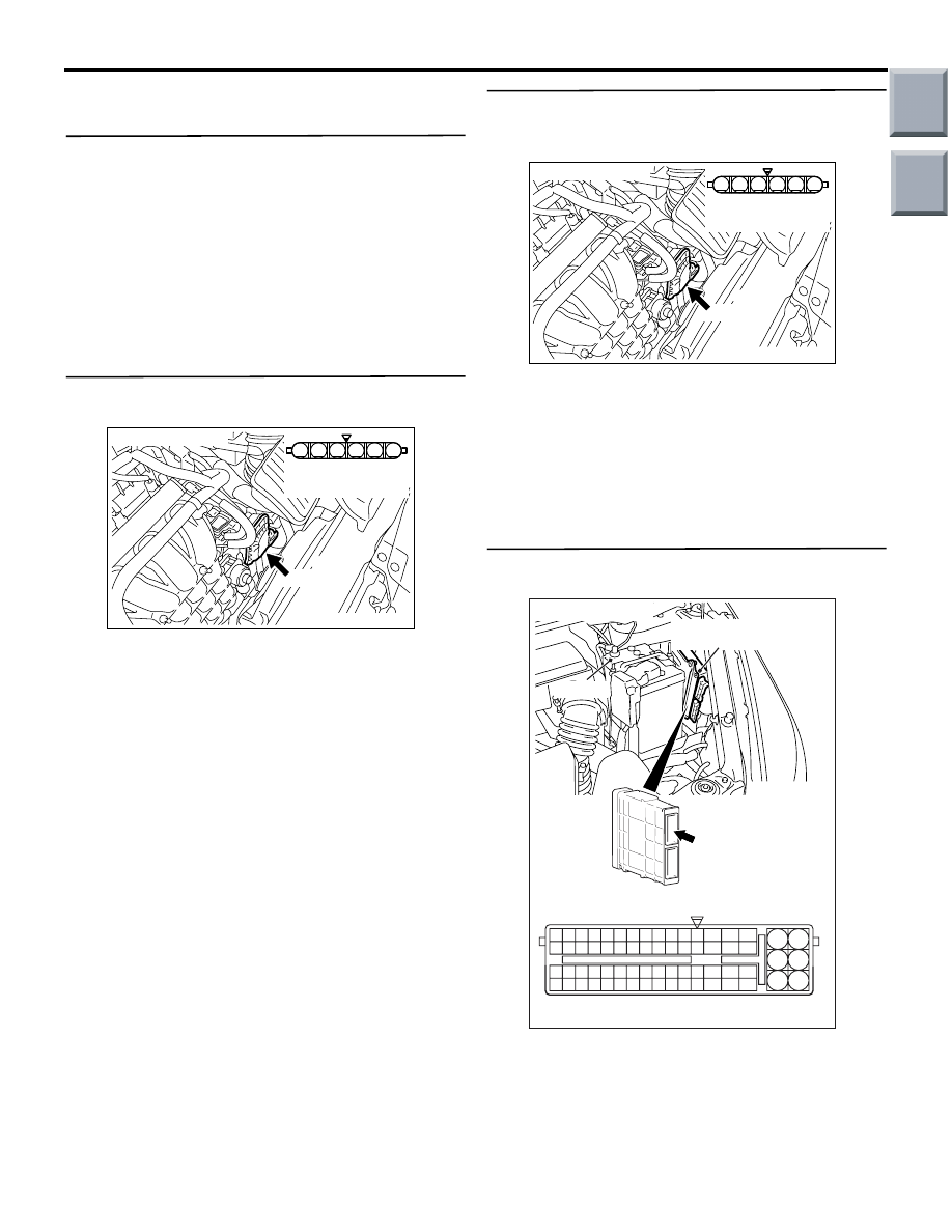
STEP 2. Connector check: A-107 
electronic-controlled throttle valve connector

Q: Is the check result normal?

YES : 

Go to Step 3 .

NO : 

Repair or replace the connector.

STEP 3. Perform resistance measurement at 
A-107 electronic-controlled throttle valve 
connector.

• Disconnect connector, and measure at harness 

side.

• Resistance between terminal No. 3 and earth.

OK: Continuity (2 

 or less)

Q: Is the check result normal?

YES : 

Go to Step 7 .

NO : 

Go to Step 4 .

STEP 4. Connector check: A-114 engine-ECU 
connector or engine-CVT-ECU connector

Q: Is the check result normal?

YES : 

Go to Step 5 .

NO : 

Repair or replace the connector.

AK402006

1

6 5 4 3 2

AC

A-107 (B)

Connector: A-107

A-107 Harness side
connector

AK402006

1

6 5 4 3 2

AC

A-107 (B)

Connector: A-107

A-107 Harness side
connector

AK402745

6

4

2

5

3

1

9

7

8

10

11

12

13

14

15

16

17

18

19

20

21

22

23

24

25

26

27

28

29

30

31

32

33

34

35

36

37

38

39

40

41

42

43

44

45

46

47

48

49

50

51

52

53

54

55

56

57

58

59

60

61

62

63

64

65

66

L

AD

A-114

Connector: 

A-114

Harness side connector

Engine-ECU <M/T> or
engine-CVT-ECU <CVT>

Battery

Main

Index

Group

TOC

TROUBLESHOOTING

MULTIPORT FUEL INJECTION (MPI) <4A9>

13A-115

STEP 5. Check harness between A-107 (terminal 
No. 3) electronic-controlled throttle valve 
connector and A-114 (terminal No. 30) 
engine-ECU connector or engine-CVT-ECU 
connector.

• Check earthing line for open circuit and damage.

Q: Is the check result normal?

YES : 

Go to Step 6 .

NO : 

Repair the damaged harness wire.

STEP 6. M.U.T.-III data list

• Refer the to Data List Reference Table 

P.13A-331

.

a. Item 14: Throttle position sensor (sub)

Q: Is the check result normal?

YES : 

Intermittent malfunction (Refer to GROUP 

00 

− How to Use Troubleshooting/Inspection 

Service Points 

− How to Cope with 

Intermittent Malfunctions 

P.00-13

).

NO : 

Replace the engine-ECU <M/T> or 
engine-CVT-ECU <CVT>.

STEP 7. Replace the throttle body assembly

• After replacing the throttle body assembly, 

re-check the trouble symptoms.

Q: Is the check result normal?

YES : 

Check end.

NO : 

Replace the engine-ECU <M/T> or 
engine-CVT-ECU <CVT>.

AK402006

1

6 5 4 3 2

AC

A-107 (B)

Connector: A-107

A-107 Harness side
connector

AK402745

6

4

2

5

3

1

9

7

8

10

11

12

13

14

15

16

17

18

19

20

21

22

23

24

25

26

27

28

29

30

31

32

33

34

35

36

37

38

39

40

41

42

43

44

45

46

47

48

49

50

51

52

53

54

55

56

57

58

59

60

61

62

63

64

65

66

L

AD

A-114

Connector: 

A-114

Harness side connector

Engine-ECU <M/T> or
engine-CVT-ECU <CVT>

Battery

Main

Index

Group

TOC

TROUBLESHOOTING

MULTIPORT FUEL INJECTION (MPI) <4A9>

13A-116

Code No. P0300: Random/Multiple Cylinder Misfire Detected

OPERATION

• Refer to Code No. P0201: No. 1 injector system 

P.13A-89

.

• Refer to Code No. P0202: No. 2 injector system 

P.13A-94

.

• Refer to Code No. P0203: No. 3 injector system 

P.13A-99

.

• Refer to Code No. P0204: No. 4 injector system 

P.13A-104

.

FUNCTION

• If a misfire occurs while the engine is running, the 

engine speed changes for an instant.

• The engine-ECU <M/T> or engine-CVT-ECU 

<CVT> checks for such changes in engine 
speed.

TROUBLE JUDGMENT

Check Conditions

• Engine speed is 500 − 4,500 r/min.

• Engine coolant temperature is −10°C or higher.

• The intake manifold pressure is above 30 kPa 

<M/T>.

• Barometric pressure is 76 kPa or higher <CVT>

• Volumetric efficiency is between 30 % and 55 % 

<CVT>.

• Adaptive learning is complete for the vane which 

generates a crankshaft position signal.

• While the engine is running, excluding gear shift-

ing, deceleration, sudden acceleration/decelera-
tion and A/C compressor switching.

• The throttle deviation is −0.06 V/10 ms to +0.06 

V/10 ms.

Judgment Criteria (change in the angular accel-

eration of the crankshaft is used for misfire 
detection).

• Misfire has occurred more frequently than the 

limit during the last 200 revolutions (when the cat-
alyst temperature has been 950

°C or higher).

or

• Misfire has occurred 15 times or more in the last 

1,000 revolutions (that has been equivalent to 
approximately 1.5 times the emission standard).

PROBABLE CAUSES

• Ignition system related part(s) failed

• Failed crank angle sensor

• Incorrect air-fuel ratio

• Low compression pressure

• Failed engine coolant temperature sensor

• Skipping of timing belt teeth.

• EGR system and EGR valve failed <CVT>

• Failed engine-ECU <M/T> or engine-CVT-ECU 

<CVT>

DIAGNOSIS PROCEDURE

STEP 1. M.U.T.-III data list 

• Item 22: Crank angle sensor

OK: Keep the engine speed constant to make 
the pulse width of output waveform con-
stant.

Q: Is the check result normal?

YES : 

Go to Step 2 .

NO : 

Check crank angle sensor system (Refer to 
Code No. P0335 

P.13A-134

).

STEP 2. M.U.T.-III data list

• Refer to Data List Reference Table 

P.13A-331

.

a. Item 21: Engine coolant temperature sensor
b. Item 81: Long-term fuel compensation

c. Item 82: Short-term fuel compensation

Q: Are the check results normal?

YES : 

 Go to Step 3 .

NO : 

Perform the diagnosis code classified check 
procedure for the sensor that has shown an 
abnormal data valve (Refer to Inspection 
Chart for Diagnosis Code 

P.13A-20

).

STEP 3. Visual check of ignition spark.

• Remove the spark plug and install it to the ignition 

coil.

• Connect the ignition coil connector.

• Remove all injector connector.

• At the engine start, check each spark plug pro-

duces a spark.

Q: Is the check result normal?

YES : 

 Go to Step 4 .

NO : 

Check ignition circuit system (Refer to 
Inspection Procedure 28 

P.13A-320

).

Main

Index

Group

TOC

TROUBLESHOOTING

MULTIPORT FUEL INJECTION (MPI) <4A9>

13A-117

STEP 4. Connector check: Injector connector

a. A-102 (No. 1 injector connector)
b. A-103 (No. 2 injector connector)

c. A-104 (No. 3 injector connector)

d. A-105 (No. 4 injector connector)

Q: Are the check results normal?

YES : 

Go to Step 5 .

NO : 

Repair or replace.

STEP 5. Check injector itself. 

• Check Injector itself (Refer to 

P.13A-364

).

Q: Is the check result normal?

YES : 

 Go to Step 6 .

NO : 

Replace injector.

STEP 6. Fuel pressure measurement.

• Fuel pressure measurement (Refer to Fuel Pres-

sure Test 

P.13A-355

)

Q: Is the check result normal?

YES : 

 Go to Step 7 .

NO : 

Repair.

STEP 7. Check for intake of air from intake hose 
and inlet manifold.

Q: Is the check result normal?

YES : 

 Go to Step 8 .

NO : 

Repair.

STEP 8. Check for skipped timing belt teeth.

Q: Is the check result normal?

YES : 

 Go to Step 9 <CVT> , go to Step 10 <M/T> 

NO : 

Repair.

STEP 9. Check EGR valve (stepper motor) itself.

• Check EGR valve (stepper motor) itself [Refer to 

GROUP 17 

− Exhaust Gas Recirculation (EGR) 

System 

− EGR Valve (Stepper Motor) Check 

P.17-20

].

Q: Is the check result normal?

YES : 

 Go to Step 10 .

NO : 

Replace EGR valve (stepper motor)

STEP 10. Check the trouble symptoms.

Q: Does trouble symptom persist?

YES : 

Replace engine-ECU <M/T> or 

engine-CVT-ECU <CVT>.

NO : 

Intermittent malfunction (Refer to Group 00 

− 

How to Use Troubleshooting/Inspection 
Service Points 

− How to Cope with 

Intermittent Malfunctions 

P.00-13

).

AK503594

M

1

2

A-104 (G)

A-103 (G)

A-102 (G)

A-105 (G)

Connectors: A-102, A-103, A-104, A-105

Harness side
connector

AB

Main

Index

Group

TOC


Content   ..  38  39  40  41   ..