Mitsubishi Colt Ralliart. Manual - part 25


  Index      Mitsubishi     Mitsubishi Colt Ralliart - service repair manual


Search            


Content   ..  23  24  25  26   ..


Mitsubishi Colt Ralliart. Manual - part 25


TROUBLESHOOTING

MULTIPORT FUEL INJECTION (MPI) <4A9>

13A-54

Code No. P0123: Throttle Position Sensor  (Main) Circuit High Input
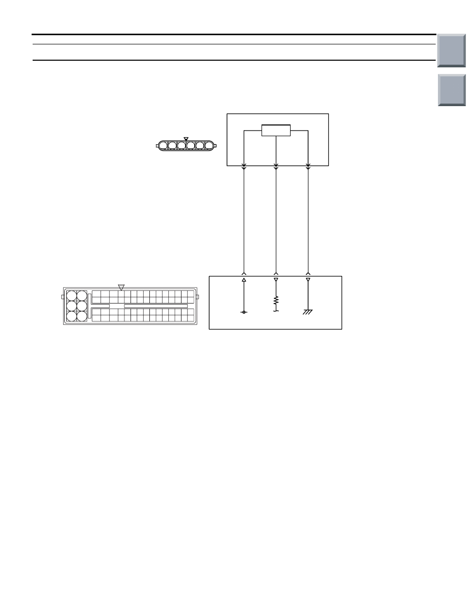
OPERATION

• A power voltage of 5 V is applied to the elec-

tronic-controlled throttle valve (terminal No. 5) 
from the engine-ECU <M/T> or engine-CVT-ECU 
<CVT> (terminal No. 31).

• The power voltage is earthed to the engine-ECU 

<M/T> or engine-CVT-ECU <CVT> (terminal No. 
30) from the electronic-controlled throttle valve 
(terminal No. 3).

• The sensor signal is inputted to the engine-ECU 

<M/T> or engine-CVT-ECU <CVT> (terminal No. 
15) from the electronic-controlled throttle valve 
output terminal (terminal No. 6).

FUNCTION

• The throttle position sensor converts the throttle 

valve position into voltage and inputs it into the 
engine-ECU <M/T> or engine-CVT-ECU <CVT>.

• The engine-ECU <M/T> or engine-CVT-ECU 

<CVT> controls the throttle valve position.

TROUBLE JUDGMENT

Check Condition

• Ignition switch is in "ON" position.

Judgment Criteria

• Throttle position sensor (main) output voltage is 

4.8 V or more <M/T>.

• Throttle position sensor (main) output voltage is 

4.8 V or more for 0.5 second <CVT>.

PROBABLE CAUSES

• Failed throttle position sensor (main)

• Open/short circuit in throttle position sensor cir-

cuit or loose connector contact

• Failed engine-ECU <M/T> or engine-CVT-ECU 

<CVT>

AK402679

6

1 2 3 4 5

19

21

20

18

17

16

15

14

1213

11

8 9

L

10

37
52 53 54 555657585960616263646566

38 39 404142434445464748495051

22 23 24 252627282930313233343536

7

5

3

1

6

4

2

5 V

31

5

Electronic-controlled
throttle valve

B-W

R-W

Y-R

Engine-ECU <M/T> or
engine-CVT-ECU <CVT>

15

30

6

3

Throttle Position Sensor (main) Circuit

A-107

A-114

(main)

Hall IC

AE

Wire colour code
B: Black  LG: Light green  G: Green  L: Blue  W: White  Y: Yellow  SB: Sky blue  BR: Brown  O: Orange  GR: Gray
R: Red  P: Pink  V: Violet  Pu: Purple

Main

Index

Group

TOC

TROUBLESHOOTING

MULTIPORT FUEL INJECTION (MPI) <4A9>

13A-55

DIAGNOSIS PROCEDURE

STEP 1. M.U.T.-III data list

• Refer to Data List Reference Table 

P.13A-331

.

a. Item 79: Throttle position sensor (main)

Q: Is the check result normal?

YES : 

Intermittent malfunction (Refer to GROUP 

00 

− How to Use 

Troubleshooting/Inspection Service Points 

− 

How to Cope with Intermittent Malfunctions 

P.00-13

).

NO : 

Go to Step 2 .

STEP 2. Connector check: A-107 
electronic-controlled throttle valve connector

Q: Is the check result normal?

YES : 

Go to Step 3 .

NO : 

Repair or replace the connector.

STEP 3. Perform resistance measurement at 
A-107 electronic-controlled throttle valve 
connector.

• Disconnect connector, and measure at harness 

side.

• Resistance between terminal No. 3 and earth.

OK: Continuity (2 

 or less)

Q: Is the check result normal?

YES : 

Go to Step 7 .

NO : 

Go to Step 4 .

STEP 4. Connector check: A-114 engine-ECU 
connector or engine-CVT-ECU connector

Q: Is the check result normal?

YES : 

Go to Step 5 .

NO : 

Repair or replace the connector.

AK402006

1

6 5 4 3 2

AC

A-107 (B)

Connector: A-107

A-107 Harness side
connector

AK402006

1

6 5 4 3 2

AC

A-107 (B)

Connector: A-107

A-107 Harness side
connector

AK402745

6

4

2

5

3

1

9

7

8

10

11

12

13

14

15

16

17

18

19

20

21

22

23

24

25

26

27

28

29

30

31

32

33

34

35

36

37

38

39

40

41

42

43

44

45

46

47

48

49

50

51

52

53

54

55

56

57

58

59

60

61

62

63

64

65

66

L

AD

A-114

Connector: 

A-114

Harness side connector

Engine-ECU <M/T> or
engine-CVT-ECU <CVT>

Battery

Main

Index

Group

TOC

TROUBLESHOOTING

MULTIPORT FUEL INJECTION (MPI) <4A9>

13A-56

STEP 5. Check harness between A-107 (terminal 
No. 3) electronic-controlled throttle valve 
connector and A-114 (terminal No. 30) 
engine-ECU connector or engine-CVT-ECU 
connector.

• Check earthing line for open circuit and damage.

Q: Is the check result normal?

YES : 

Go to Step 6 .

NO : 

Repair the damaged harness wire.

STEP 6. M.U.T.-III data list

• Refer to Data List Reference Table 

P.13A-331

.

a. Item 79: Throttle position sensor (main)

Q: Is the check result normal?

YES : 

Intermittent malfunction (Refer to GROUP 

00 

− How to Use Troubleshooting/Inspection 

Service Points 

− How to Cope with 

Intermittent Malfunctions 

P.00-13

).

NO : 

Replace the engine-ECU <M/T> or 
engine-CVT-ECU <CVT>.

STEP 7. Replace the throttle body assembly

• After replacing the throttle body assembly, 

re-check the trouble symptoms.

Q: Is the check result normal?

YES : 

Check end.

NO : 

Replace the engine-ECU <M/T> or 
engine-CVT-ECU <CVT>.

AK402006

1

6 5 4 3 2

AC

A-107 (B)

Connector: A-107

A-107 Harness side
connector

AK402745

6

4

2

5

3

1

9

7

8

10

11

12

13

14

15

16

17

18

19

20

21

22

23

24

25

26

27

28

29

30

31

32

33

34

35

36

37

38

39

40

41

42

43

44

45

46

47

48

49

50

51

52

53

54

55

56

57

58

59

60

61

62

63

64

65

66

L

AD

A-114

Connector: 

A-114

Harness side connector

Engine-ECU <M/T> or
engine-CVT-ECU <CVT>

Battery

Main

Index

Group

TOC

TROUBLESHOOTING

MULTIPORT FUEL INJECTION (MPI) <4A9>

13A-57

Code No. P0125: Feedback System Monitor

OPERATION

• Refer to Code No. P0201 No. 1 Injector System 

P.13A-89

.

Refer to Code No. P0202 No. 2 Injector System 

P.13A-94

.

Refer to Code No. P0203 No. 3 Injector System 

P.13A-99

.

Refer to Code No. P0204 No. 4 Injector System 

P.13A-104

.

• Refer to Code No. P0130 Oxygen Sensor (Front) 

Circuit 

P.13A-62

.

FUNCTION

• The engine-ECU <M/T> or engine-CVT-ECU 

<CVT> effects air-fuel ratio feedback control in 
accordance with the signals from the oxygen sen-
sor (front).

• If the oxygen sensor (front) has deteriorated, cor-

rections will be made by the oxygen sensor 
(rear).

• Diagnosis code P0125 becomes stored in mem-

ory if a failure is detected in the above air/fuel 
ratio feedback control system.

TROUBLE JUDGMENT

Check Conditions

• Above 30 seconds later after the engine has 

started up <M/T>.

• The engine coolant temperature approximately. 

82

°C or more.

• Within the range of air-fuel ratio feedback opera-

tion.

• Not in low speed operation.

Judgment Criterion

• The oxygen sensor output voltage is not deviated 

from 0.5 V for 30 seconds.

PROBABLE CAUSES

• Failed oxygen sensor (front)

• Harness damage in oxygen sensor (front) circuit 

or loose connector contact

• Failed oxygen sensor (rear)

NOTE: When the oxygen sensor (front) begins to 
deteriorate, the oxygen sensor output voltage will 
deviate from the voltage when the sensor was new 
(normally 0.5 volt at stoichiometric ratio). This devia-
tion will be corrected by the oxygen sensor (rear).If 
the oxygen sensor (rear) responds poorly because it 

has deteriorated, it will improperly correct the oxygen 
sensor (front). Thus, even when closed loop control 
is being effected, the fluctuation of the oxygen sen-
sor (front) output voltage decreases, without inter-
secting with 0.5 volt. As a result, there is a possibility 
of diagnosis code P0125 becoming registered.

• Failed fuel system

• Failed exhaust system

• Air drawn in from gaps in gasket, seals, etc

• Failed engine-ECU <M/T> or engine-CVT-ECU 

<CVT>

DIAGNOSIS PROCEDURE

STEP 1. M.U.T.-III diagnosis code

Q: Is any other diagnosis code than P0125 output?

YES : 

Inspection chart for diagnosis code (Refer 

to 

P.13A-20

).

NO : 

Go to Step 2 .

STEP 2. M.U.T.-III data list

• Refer to Data List Reference Table 

P.13A-331

.

a. Item 21: Engine coolant temperature sensor
b. Item 32: Manifold absolute pressure sensor

c. Item 59: Oxygen sensor (rear)

Q: Are the check results normal?

YES : 

 Go to Step 3 .

NO : 

Perform the diagnosis code classified check 
procedure for the sensor that has shown an 
abnormal data valve (Refer to Inspection 
Chart for Diagnosis Code 

P.13A-20

).

STEP 3. Check for intake of air from gaps in 
gasket, seals, etc.

Q: Is the check result normal?

YES : 

 Go to Step 4 .

NO : 

Repair for intake of air from gaps in gasket, 
seals, etc.

STEP 4. Check for leakage of exhaust emission 
from exhaust manifold.

Q: Is the check result normal?

YES : 

Go to Step 5 .

NO : 

Repair for leakage of exhaust emission from 
exhaust manifold.

Main

Index

Group

TOC


Content   ..  23  24  25  26   ..