Mitsubishi Colt Ralliart. Manual - part 14


  Index      Mitsubishi     Mitsubishi Colt Ralliart - service repair manual


Search            


Content   ..  12  13  14  15   ..


Mitsubishi Colt Ralliart. Manual - part 14


TROUBLESHOOTING

MULTIPORT FUEL INJECTION (MPI) <4A9>

13A-10

TROUBLESHOOTING

DIAGNOSIS TROUBLESHOOTING FLOW

M1131150001390

Refer to 

P.00-13

, GROUP 00 

− How to Use Trouble-

shooting/Inspection Service Points 

− How to Cope 

with Intermittent Malfunctions.

DIAGNOSIS FUNCTION

M1131155501840

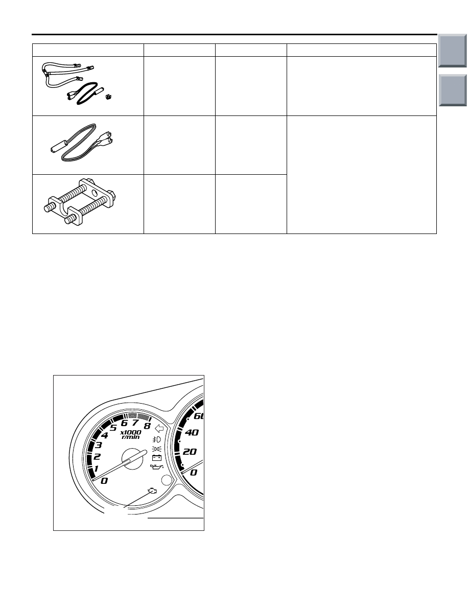
ENGINE WARNING LAMP (CHECK 
ENGINE LAMP)

If an abnormality occurs in any of the following items 
related to the Multipoint Fuel Injection (MPI) system, 
the engine warning lamp will illuminate.
If the lamp remains illuminated or if the lamp illumi-
nates while the engine is running, check the diagno-
sis code output.

MD998706

Injector test set

• Measurement of fuel pressure

• Checking the spray condition of 

injectors

MB991607

Injector test 
harness

Checking the spray condition of 
injector

MB991976

Injector test 
holder assembly

Tool

Number

Name

Use

MD998706

MB991607

MB991976

AK402082AD

Engine
warning lamp

Main

Index

Group

TOC

TROUBLESHOOTING

MULTIPORT FUEL INJECTION (MPI) <4A9>

13A-11

ENGINE WARNING LAMP INSPECTION ITEMS

Code No.

Diagnosis item

Engine-ECU <M/T> or engine-CVT-ECU <CVT>

P0105

Manifold absolute pressure sensor system

P0110

Intake air temperature sensor system

P0115

Engine coolant temperature sensor system

P0122*

Throttle position sensor (main) circuit low input

P0123*

Throttle position sensor (main) circuit high input

P0125*

Feedback system monitor

P0130

Oxygen sensor (front) system

P0135

Oxygen sensor (front) heater system

P0136

Oxygen sensor (rear) system

P0141

Oxygen sensor (rear) heater system

P0170

Abnormal fuel system

P0201

No. 1 injector system

P0202

No. 2 injector system

P0203

No. 3 injector system

P0204

No. 4 injector system

P0222*

Throttle position sensor (sub) circuit low input

P0223*

Throttle position sensor (sub) circuit high input

P0300*

Random/multiple cylinder misfire detected

P0301*

No. 1 cylinder misfire detected

P0302*

No. 2 cylinder misfire detected

P0303*

No. 3 cylinder misfire detected

P0304*

No. 4 cylinder misfire detected

P0325

Detonation sensor system

P0335

Crank angle sensor system

P0340

Camshaft position sensor system

P0403

Exhaust gas recirculation control system <CVT>

P0421

Warm up catalyst malfunction 

P0443

Purge control solenoid valve system

P0500

Vehicle speed signal system <M/T>

P0606

Microcomputer malfunction system <CVT>

P0638*

Throttle valve control servo circuit range/performance problem

P0642*

Throttle position sensor power supply

P0657*

Throttle valve control servo relay circuit malfunction

P1021

Oil control valve system

P1602*

Communication malfunction (between engine-ECU <M/T> or engine-CVT-ECU 
<CVT> main processor and system LSI)

P1603*

Battery backup circuit malfunction

P2100*

Throttle valve control servo circuit (open)

P2101*

Throttle valve control servo magneto malfunction

Main

Index

Group

TOC

TROUBLESHOOTING

MULTIPORT FUEL INJECTION (MPI) <4A9>

13A-12

NOTE: 

.

If the engine warning lamp illuminates because of a malfunction of the engine-ECU <M/T> or 
engine-CVT-ECU <CVT>, communication between M.U.T.-III and the engine-ECU <M/T> or 
engine-CVT-ECU <CVT> is impossible. In this case, the diagnosis code cannot be read.

After the engine-ECU <M/T> or engine-CVT-ECU <CVT> has detected a malfunction, the engine warning 
lamp illuminates when the engine is next turned on and the same malfunction is re-detected.However, for 
items marked with a "*" in the diagnosis code number column, the engine warning lamp illuminates only 
on the first detection of the malfunction.

After the engine warning lamp illuminates, it will be switched off under the following conditions.

When the engine-ECU <M/T> or engine-CVT-ECU <CVT> monitored the power train malfunction 
three times* met set condition requirements, it detected no malfunction.

*: In this case, "one time" indicates from engine start to stop.

For misfiring malfunction, when driving conditions (engine speed, engine coolant temperature, etc.) 
are similar to those when the malfunction was first recorded.

Sensor 1 indicates, the sensor mounted at a position closest to the engine, and sensor 2 indicates the 
sensor mounted at the position second closest to the engine.

METHOD OF READING AND ERASING 
DIAGNOSIS CODES

Refer to 

P.00-7

, GROUP 00 

− How to Use Trouble-

shooting/Inspection Service Points 

− Diagnosis 

Function.

DIAGNOSIS USING DIAGNOSIS 2 MODE

1. Switch the diagnosis mode of the engine control 

unit to DIAGNOSIS 2 mode using the M.U.T.-III.

2. Carry out a road test.
3. Take a reading of the diagnosis code and repair 

the problem location.

4. Turn the ignition switch to OFF and then back to 

ON again.

NOTE: . By turning the ignition switch to OFF, the 

engine-ECU <M/T> or engine-CVT-ECU <CVT> 
will switch the diagnosis mode from DIAGNOSIS 
2 mode to DIAGNOSIS 1 mode.

5. Erase the diagnosis codes.

INSPECTION USING M.U.T.-III DATA LIST 
AND ACTUATOR TESTING

1. Carry out inspection by means of the data list and 

the actuator test function, if there is an 
abnormality, check and repair the chassis harness 
and components.

2. After repairing, re-check using the M.U.T.-III and 

check that the abnormal input and output have 
returned to normal as a result of the repairs.

3. Erase the diagnosis code memory.
4. Remove the M.U.T.-III, and then start the engine 

again and carry out a road test to confirm that the 
problem has disappeared.

P2108*

Throttle valve control servo processor malfunction

P2122*

Accelerator pedal position sensor (main) circuit low input

P2123*

Accelerator pedal position sensor (main) circuit high input

P2127*

Accelerator pedal position sensor (sub) circuit low input

P2128*

Accelerator pedal position sensor (sub) circuit high input

P2135*

Throttle position sensor (main and sub) range/performance problem

P2138*

Accelerator pedal position sensor (main and sub) range/performance problem

P2226

Barometric pressure sensor system

U1108

Combination meter time-out

Code No.

Diagnosis item

Main

Index

Group

TOC

TROUBLESHOOTING

MULTIPORT FUEL INJECTION (MPI) <4A9>

13A-13

FREEZE FRAME DATA

When the engine-ECU <M/T> or engine-CVT-ECU 
<CVT> detects a malfunction and stores a diagnosis 
code, it also stores a current status of the engine. 
This function is called "Freeze frame data". By ana-
lyzing this "Freeze frame" data with the M.U.T.-III, an 
effective troubleshooting can be performed.
The display items of freeze frame data are shown 
below.

DISPLAY ITEM LIST

NOTE: If malfunctions have been detected in multiple systems, store one malfunction only, which has been 
detected first.

Item No.

Data

Unit

13

Intake air temperature sensor

°C

21

Engine coolant temperature sensor

°C

22

Crank angle sensor

r/min

24

Vehicle speed

km/h

32

Manifold absolute pressure sensor

kPa

44

Ignition advance

deg

81

Long-term fuel compensation 

%

82

Short-term fuel compensation

%

87

Calculation load value

%

88

Fuel control condition 

Open loop

OL

Closed loop

CL

Open loop owing to drive condition

OL-DRV.

Open loop owing to system malfunction

OL-SYS.

Closed loop based on one oxygen sensor

CL-H02S

89

Fuel control condition

A1

Oxygen sensor (front)

V

A2

Oxygen sensor (rear)

V

Main

Index

Group

TOC


Content   ..  12  13  14  15   ..