Mitsubishi 380. Manual - part 966


  Index      Mitsubishi     Mitsubishi 380 - service repair manual 2005 year


Search            


Content   ..  964  965  966  967   ..


Mitsubishi 380. Manual - part 966


ON-VEHICLE SERVICE

ANTI-LOCK BRAKING SYSTEM (ABS)

35B-89

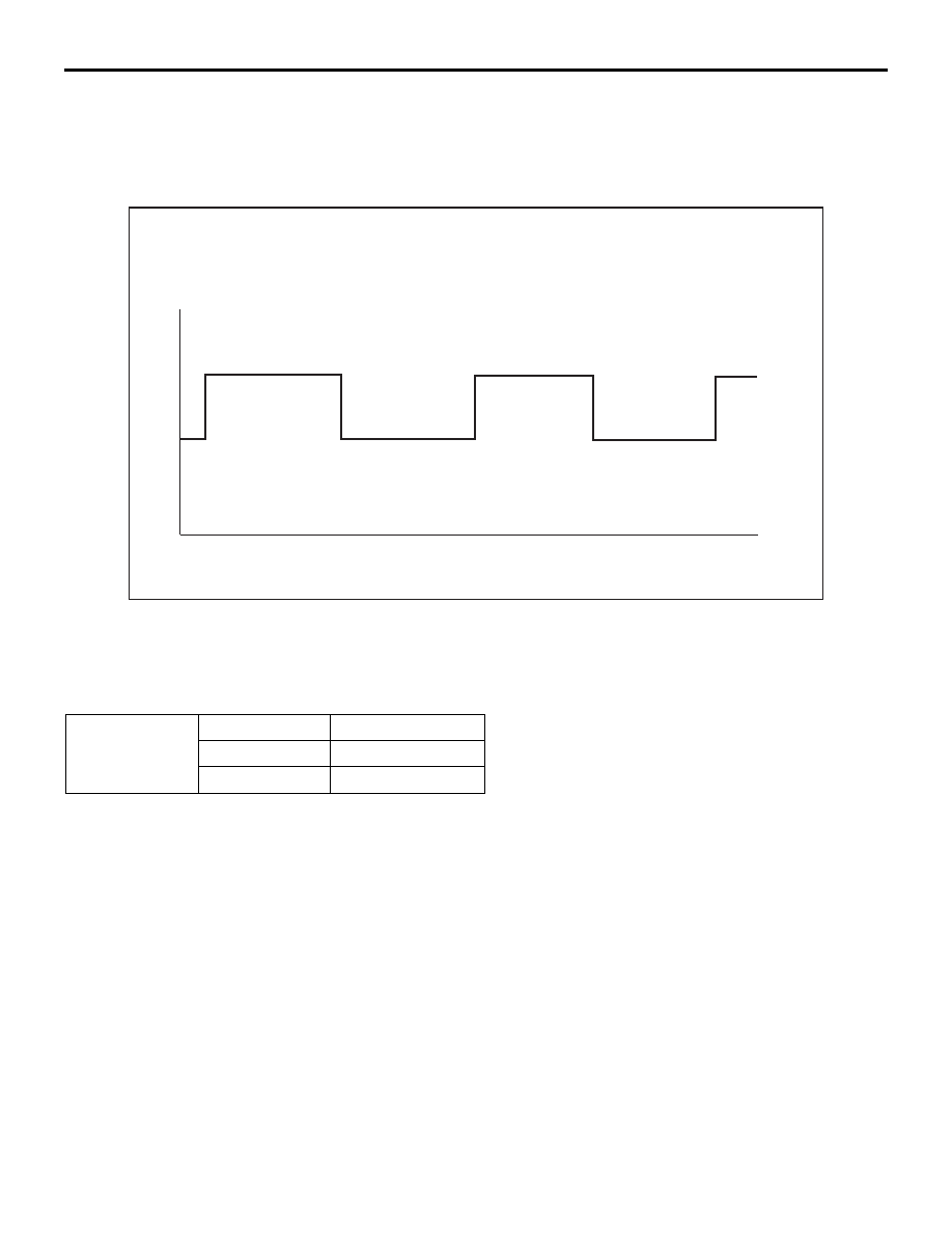
6. Turn wheel by hand at approximately 1 revolution per 

second (r/sec) or drive on brake dynamometer at 5km/h.
Recommended Oscilloscope setting:

•  Y-axis:  2Volts

•  X-axis:  100ms

NOTE: If the oscilloscope signal shape is correct and wheel 
sensor air gap is within specification, but the voltage values are 
either higher or lower as shown in the table below, the wheel 
speed sensor must be changed. 

Probable causes of low output voltage

• Wheel speed sensor pole piece to wheel speed rotor clear-

ance too large

• Faulty wheel speed sensor

7. To observe the waveform with an oscilloscope:

• Front and Rear Wheels: Turn the wheels manually at a con-

stant speed

NOTE: The output voltage will remain same regardless of 
vehicle speed.

.

NOTE: The wheel speed sensor cable moves in relation to motion of the front or rear suspension. Therefore, 
it is likely that it has an open circuit only when driving on rough roads but it functions normally when driving on 
smooth roads. It is recommended to observe sensor signal waveform also under special conditions, such as 
driving on a rough road.

1.50

1.00

0.50

0.00

U-CH1

0

20

40

60

80

100

ms

V

Test Procedure:   Universal Oscilloscope

FIGURE  3

35DB120A

Wheel speed 
sensor

    Standard

        Value

High

0.9V - 1.5V

Low

0.3V - 0.8V

ON-VEHICLE SERVICE

ANTI-LOCK BRAKING SYSTEM (ABS)

35B-90

HYDRAULIC UNIT CHECK

M1352001700512

Required Special Tools:

• MB991958: MUT-III Sub Assembly

• MB991824: Vehicle Communication Interface (V.C.I.)

• MB991827: MUT-III USB Cable

• MB991910: MUT-III Main Harness A (Vehicles with CAN 

communication system)

CAUTION

• The roller of the braking force tester and the tyre 

should be dry during testing.

• When testing the front brakes, apply the parking brake. 

When testing the rear brakes, stop the front wheels 
with chocks.

1. Jack up the vehicle. Then support the vehicle with rigid 

racks at the specified jack-up points or place the front or rear 
wheels on the rollers of the braking force tester.

2. Release the parking brake, and feel the drag force (drag 

torque) on each road wheel. When using the braking force 
tester, take a reading of the brake drag force.

CAUTION

To prevent damage to diagnostic tool MB991958, always 
turn the ignition switch to the "LOCK" (OFF) position 
before connecting or disconnecting diagnostic tool 
MB991958.
3. Connect diagnostic tool MB991958 to the data link 

connector.

4. After checking that the selector lever is in "P" range, start the 

engine.

5. Select "Interactive Diagnosis" from the start-up screen.

6. Select "System Select."

7. Choose "ABS" .

8. Select "Actuator Test" from "ABS" screen

9. Choose an appropriate item for hydraulic unit check.

NOTE: The ABS system will switch to the diagnostic tool 
mode and the ABS warning light will illuminate.

NOTE: When the ABS has been interrupted by the fail-safe 
function, diagnostic tool MB991958 actuator testing cannot 
be used.

00DB076A

MB991910

DATA LINK

CONNECTOR

MB991824

MB991827

ON-VEHICLE SERVICE

ANTI-LOCK BRAKING SYSTEM (ABS)

35B-91

10.Turn the wheel by hand and check the change in braking 

force when the brake pedal is depressed. When using the 
braking force tester, depress the brake pedal until the 
braking force is at the following values, and check that the 
braking force changes to the brake drag force reading taken 
in step 2 when the actuator is force-driven. The result should 
be as shown in the diagram above.

11.If the result of inspection is abnormal, repair according to the 

Diagnosis Table below.

Front wheel

785 

− 981 N (176 − 220 lb.)

Rear wheel

588 

− 784 N (132 − 176 lb.)

AC000954AB

SCAN TOOL ACTUATOR TEST

(ITEM NO.01, 02, 03, 04) START

1 s

2 s

3 s

DEPRESSED

RELEASED

PRESSURE INCREASE

PRESSURE DECREASE

PRESSURE HOLD

LOCK

DRAG FORCE

WHEN THE

PEDAL IS FREE

PEDAL

OPERATION

SOLENOID

VALVE

POSITION

CHECKING

THE BRAKE

FORCE

ON-VEHICLE SERVICE

ANTI-LOCK BRAKING SYSTEM (ABS)

35B-92

12.After inspection, disconnect diagnostic tool MB991958 

immediately after turning the ignition switch to the "LOCK" 
(OFF) position. 

IN THE EVENT OF A DISCHARGED BATTERY

M1352003500547

WARNING

If the ABS is not operating, the vehicle will be unsta-
ble during braking, Do not drive the vehicle with the 
ABS-ECU connector disconnected or with the ABS 
not operating.

If the engine is started using a booster cable when the battery 
is completely flat, and the vehicle is then driven without waiting 
for the battery to be recharged, the engine may misfire and it 
may not be possible to drive the vehicle. This is because the 
ABS consumes a large amount of current when carrying out its 
initial checks. If this happens, recharge the battery fully.

DIAGNOSIS TABLE

MUT-III 
DISPLAY

OPERATION

INSPECTION 
RESULT

JUDGMENT PROBABLE 

CAUSE

REMEDY

01 FL VALVE
02 FR VALVE
03 RL VALVE
04 RR VALVE

• Depress brake 

pedal to lock 
wheel.

• Using diagnostic 

tool MB991958, 
select the wheel to 
be checked and 
force the actuator 
to operate.

• Turn the selected 

wheel manually to 
check the change 
of brake force.

Brake force is 
released for 
three seconds 
after wheels 
have been 
locked.

Normal

Wheel does not 
lock when brake 
pedal is 
depressed.

Abnormal

Clogged brake 
line other than 
hydraulic unit

Check and clean 
brake line

Clogged 
hydraulic circuit 
in hydraulic unit

Replace 
hydraulic unit 
assembly

Brake force is 
not released

Abnormal

Incorrect 
hydraulic unit 
brake tube 
connection

Connect correctly

Hydraulic unit 
solenoid valve 
not functioning 
correctly

Replace 
hydraulic unit 
assembly


Content   ..  964  965  966  967   ..