Mitsubishi 380. Manual - part 955


  Index      Mitsubishi     Mitsubishi 380 - service repair manual 2005 year


Search            


Content   ..  953  954  955  956   ..


Mitsubishi 380. Manual - part 955


ANTI-LOCK BRAKING SYSTEM (ABS) DIAGNOSIS

ANTI-LOCK BRAKING SYSTEM (ABS)

35B-45

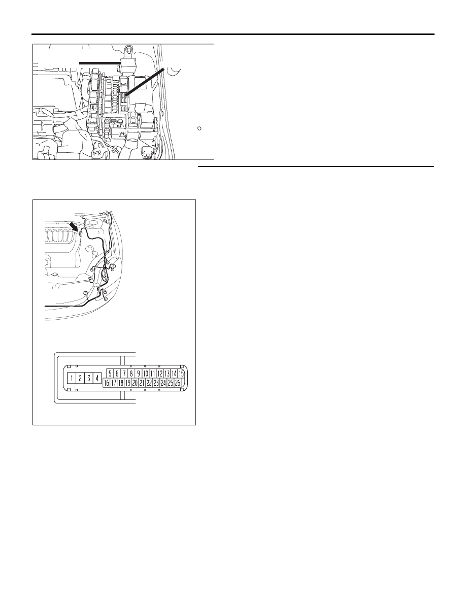
STEP 4. Check ABS-ECU connector A-02  for loose, 
corroded or damaged terminals, or terminals pushed back 
in the connector.

Q:Is ABS-ECU connector A-02 damaged?

YES : Repair or replace the damaged component(s). Refer 

to GROUP 00E, Harness Connector Inspection 

P.00E-2

. Then go to Step 8.

NO :  An open or short circuit may be present in the 

solenoid valve power supply circuit. Repair the wiring 
harness between ABS-ECU connector A-02 terminal 
3 and external (20A) fusible link.Then go to Step 8.

FUSIBLE LINK
ABS (solenoid valve)  
       (20 A) 

RELAY BOX

35DB093A

16DB402A

A-02 (GR)

CONNECTOR: A-02 

A-02 HARNESS CONNECTOR:

ANTI-LOCK BRAKING SYSTEM (ABS) DIAGNOSIS

ANTI-LOCK BRAKING SYSTEM (ABS)

35B-46

STEP 5. Measure the resistance at ABS-ECU connector 
A-02.
(1) Disconnect the connector A-02, and use special tool 

Inspection Check Harness (MB991219) to probe the wiring 
harness-side connector.

NOTE: The special tool (Inspection test harness) 
MB991219 for connector pin contact pressure should be 
used. The test probe should never be forcibly inserted, as it 
may cause a defective contact.

(2) Measure the resistance between terminal 1 and ground. It 

should be 2 ohms or less.

Q: Is the measured resistance 2 ohms or less?

YES : Go to Step 7.
NO :  Go to Step 6.

35DB094A

CONNECTOR: A-02

HYDRAULIC UNIT

(WITH BUILT-IN ABS-ECU)

TEST 

HARNESS

(MB991219)

16DB402A

A-02 (GR)

CONNECTOR: A-02 

A-02 HARNESS CONNECTOR:

ANTI-LOCK BRAKING SYSTEM (ABS) DIAGNOSIS

ANTI-LOCK BRAKING SYSTEM (ABS)

35B-47

STEP 6. Check ABS-ECU connector A-02  for loose, 
corroded or damaged terminals, or terminals pushed back 
in the connector.
Q: Is ABS-ECU connector A-02 damaged?

YES : Repair or replace the damaged component(s). Refer 

to GROUP 00E, Harness Connector Inspection 

P.00E-2

. Then go to Step 8.

NO :  An open circuit may be present in the ground circuit. 

Repair the wiring harness between ABS-ECU 
connector A-02 terminal 1 and the body ground. Then 
go to Step 8.

STEP 7. Recheck for diagnostic trouble code.
Check again if the DTC is set.
(1) Turn the ignition switch to the "ON" position.
(2) Erase the DTC.
(3) Turn the ignition switch to the "LOCK" (OFF) position.
(4) Turn the ignition switch to the "ON" position.
(5) Check if the DTC is set.
(6) Turn the ignition switch to the "LOCK" (OFF) position.

Q: Is DTC C1226, C1231, C1236, C1241, C1246, C1251, 

C1256 or C1261 set?
YES : 
Replace the hydraulic unit (integrated with 

ABS-ECU). Then go to Step 8.

NO :  It can be assumed that this malfunction is intermittent. 

Refer to GROUP 00, How to Use 
Troubleshooting/Inspection Service Points 

− How to 

Cope with Intermittent Malfunction 

P.00-14

.

16DB402A

A-02 (GR)

CONNECTOR: A-02 

A-02 HARNESS CONNECTOR:

00DB076A

MB991910

DATA LINK

CONNECTOR

MB991824

MB991827

ANTI-LOCK BRAKING SYSTEM (ABS) DIAGNOSIS

ANTI-LOCK BRAKING SYSTEM (ABS)

35B-48

STEP 8. Recheck for diagnostic trouble code.
Check again if the DTC is set.
(1) Turn the ignition switch to the "ON" position.
(2) Erase the DTC.
(3) Turn the ignition switch to the "LOCK" (OFF) position.
(4) Turn the ignition switch to the "ON" position.
(5) Check if the DTC is set.
(6) Turn the ignition switch to the "LOCK" (OFF) position.

Q: Is DTC C1226, C1231, C1236, C1241, C1246, C1251, 

C1256 or C1261 set?
YES : 
Go to Step 1.
NO :  The procedure is complete.

DTC C1266/C1273/C1274: Motor system

00DB076A

MB991910

DATA LINK

CONNECTOR

MB991824

MB991827

35DB090A

A


Content   ..  953  954  955  956   ..