Mitsubishi 380. Manual - part 891


  Index      Mitsubishi     Mitsubishi 380 - service repair manual 2005 year


Search            


Content   ..  889  890  891  892   ..


Mitsubishi 380. Manual - part 891


COMBINATION METER ASSEMBLY

CHASSIS ELECTRICAL

54A-98

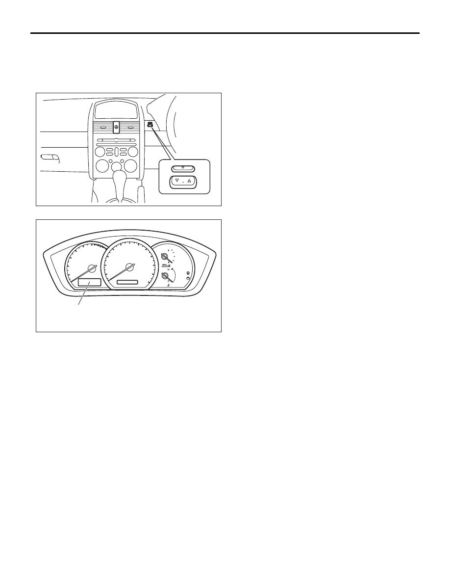
NOTE: When the mode button is pressed for the first 
time, the computer returns to the odometer function.

TROUBLESHOOTING STRATEGY

BABDEEDB

Use these steps to plan your diagnostic strategy. Fol-
low through with each step to ensure that you have 
exhausted all possible methods of finding a combina-
tion meter fault.
1. Gather information from the customer.

2. Verify that the condition described by the 

customer exists.

3. Find and repair the malfunction by following the 

symptom chart.

4. Verify that the malfunction has been eliminated.

MODE
SWITCH

16DB577A

TRIP COMPUTER
AND DISPLAY

16DB578A

COMBINATION METER ASSEMBLY

CHASSIS ELECTRICAL

54A-99

 SERVICE SPECIFICATIONS

BABJGCIC

 SERVICE REMINDER (Activation intervals)

           ITEM

  UNITS

RESOLUTION

  MININUM

   MAXIMUM

Range to empty

km

10

10

1000

Total fuel used

litres

0.1

0

199.9

1

200

2500

Average fuel consumption

litres/100km

0.1

0.1

99.9

Instantaneous fuel consumption

litres/100km

0.1

0.1

199.9

Time travelled

hh/mm

(00:01) 1 minute

0:00

199:59

Total distance travelled  (split 
resolution)

km

0.1

0

1999.9

1

2000

9999

Average speed  (split resolution)

km/h

0.1

0.0

199.9

1

200

240

Speed alarm (set speed)

km/h

5

20

195

Rest reminder

h:mm

0:01

0:30

4:00

         RESOLUTION (kms)

              MININUM (kms)

            MAXIMUM (kms)

1500

1000

2000

15000

14500

15500

30000

29500

30500

45000

44500

45500

60000

59500

60500

75000

74500

75500

90000

89500

90500

105000

104500

105500

120000

119500

120500

135000

134500

135500

150000

149500

150500

165000

164500

165500

180000

179500

180500

195000

194500

195500

210000

209500

210500

>210,000 (every 15,000 km).

500 km before every 
scheduled service thereafter

500 km after every scheduled 
service thereafter

COMBINATION METER ASSEMBLY

CHASSIS ELECTRICAL

54A-100

DIAGNOSIS FUNCTION

BABCBCFC

HOW TO CONNECT DIAGNOSTIC TOOL (MUT-III)

Required Special Tools:

• MB991958: Diagnostic Tool (MUT-III Sub Assembly)

• MB991824: Vehicle Communication Interface (V.C.I.)

• MB991827: MUT-III USB Cable

• MB991910: MUT-III Main Harness A (Vehicles with CAN 

communication system)

CAUTION

To prevent damage to diagnostic tool MB991958, always 
turn the ignition switch to the "LOCK" (OFF) position 
before connecting or disconnecting diagnostic tool 
MB991958.
1. Ensure that the ignition switch is at the "LOCK" (OFF) 

position.

2. Start up the personal computer.

3. Connect special tool MB991827 to special tool MB991824 

and the personal computer.

4. Connect special tool MB991910 to special tool MB991824.

5. Connect special tool MB991910 to the data link connector.

6. Turn the power switch of special tool MB991824 to the "ON" 

position.

NOTE: When special tool MB991824 is energized, special 
tool MB991824 indicator light will be illuminated in a green 
color.

7. Start the MUT-III system on the personal computer.

NOTE: Disconnecting the diagnostic tool MB991958 is the 
reverse of the connecting sequence, making sure that the 
ignition switch is at the "LOCK" (OFF) position.

HOW TO READ AND ERASE DIAGNOSTIC 
TROUBLE CODES

Required Special Tools:

• MB991958: Diagnostic Tool (MUT-III Sub Assembly)

• MB991824: Vehicle Communication Interface (V.C.I.)

• MB991827: MUT-III USB Cable

• MB991910: MUT-III Main Harness A (Vehicles with CAN 

communication system)

CAUTION

To prevent damage to diagnostic tool MB991958, always 
turn the ignition switch to the "LOCK" (OFF) position 
before connecting or disconnecting diagnostic tool 
MB991958.

NOTE: If the battery voltage is low, diagnostic trouble codes will 
not be set. Check the battery if diagnostic tool MB991958 does 
not display.

00DB076A

MB991910

DATA LINK

CONNECTOR

MB991824

MB991827

COMBINATION METER ASSEMBLY

CHASSIS ELECTRICAL

54A-101

1. Connect diagnostic tool MB991958 to the data link 

connector.

2. Turn the ignition switch to "ON" position.

3. Select "Interactive Diagnosis" from the start-up screen.

4. Select "System select."

5. Choose "Meter" .

6. Select "Diagnostic Trouble Code."

7. If a DTC is set, it is shown.

8. Choose "Erase DTCs" to erase the DTC.

HOW TO DIAGNOSE THE CAN BUS LINES

Required Special Tools:

• MB991958: Diagnostic Tool (MUT-III Sub Assembly)

• MB991824: Vehicle Communication Interface (V.C.I.)

• MB991827: MUT-III USB Cable

• MB991910: MUT-III Main Harness A (Vehicles with CAN 

communication system)

CAUTION

To prevent damage to diagnostic tool MB991958, always 
turn the ignition switch to the "LOCK" (OFF) position 
before connecting or disconnecting diagnostic tool 
MB991958.

00DB076A

MB991910

DATA LINK

CONNECTOR

MB991824

MB991827


Content   ..  889  890  891  892   ..