Mitsubishi 380. Manual - part 872


  Index      Mitsubishi     Mitsubishi 380 - service repair manual 2005 year


Search            


Content   ..  870  871  872  873   ..


Mitsubishi 380. Manual - part 872


IGNITION SWITCH

CHASSIS ELECTRICAL

54A-22

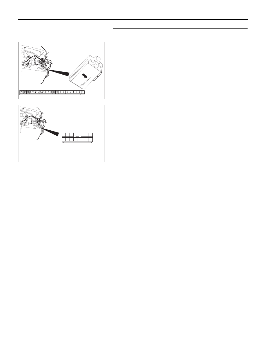
STEP 4. Check the wiring harness between ETACS-ECU 
connector C-219 (terminal 20) and battery.

NOTE: Also check junction block connector C-214 for loose, 
corroded, or damaged terminals, or terminals pushed back in 
the connector. If junction block connector C-214 is damaged, 
repair or replace the damaged component(s) as described in 
GROUP 00E, Harness Connector Inspection 

P.00E-2

.

Q: Is the wiring harness between ETACS-ECU connector 

C-219 (terminal 20) and battery in good condition?
YES : 
No action is necessary and testing is complete.
NO :  The wiring harness may be damaged or the connector 

may have loose, corroded or damaged terminals, or 
terminals pushed back in the connector. Repair the 
wiring harness as necessary. If the functions or 
equipment described in "CIRCUIT OPERATION" work 
normally, the interior light loaded signal should be 
normal.

54DB014A

CONNECTOR: C-219

JUNCTION BLOCK SIDE

JUNCTION BLOCK

(REAR VIEW)

54DB057A

CONNECTOR: C-214

HARNESS SIDE

10

1

6

14

5

12

13

4

11

7

2

3

8

9

IGNITION SWITCH

CHASSIS ELECTRICAL

54A-23

STEP 5. Check the ignition switch (IG1) line of the power 
supply circuit to the ETACS-ECU. Measure the voltage at 
ETACS-ECU connector C-219.
(1) Disconnect ETACS-ECU connector C-219 and measure the 

voltage available at the junction block side of the connector.

(2) Turn the ignition switch to the "ON" position.

(3) Measure the voltage between terminal 8 and ground.

• The voltage should measure approximately 12 volts 

(battery positive voltage).

Q: Is the measured voltage approximately 12 volts (battery 

positive voltage)?
YES : 
Go to Step 7.
NO :  Go to Step 6.

STEP 6. Check the wiring harness between ETACS-ECU 
connector C-219 (terminal 8) and the ignition switch (IG1).

54DB014A

CONNECTOR: C-219

JUNCTION BLOCK SIDE

JUNCTION BLOCK

(REAR VIEW)

AC209799

201918 171615 1413 1211 10 9 8 7 6 5 4 3 2 1

AB

CONNECTOR C-219
(JUNCTION BLOCK SIDE)

54DB014A

CONNECTOR: C-219

JUNCTION BLOCK SIDE

JUNCTION BLOCK

(REAR VIEW)

IGNITION SWITCH

CHASSIS ELECTRICAL

54A-24

NOTE: Also check junction block connector C-215 for loose, 
corroded, or damaged terminals, or terminals pushed back in 
the connector. If junction block connector C-215 is damaged, 
repair or replace the damaged component(s) as described in 
GROUP 00E, Harness Connector Inspection 

P.00E-2

.

Q: Is the wiring harness between ETACS-ECU connector 

C-219 (terminal 8) and the ignition switch (IG1) in good 
condition?
YES : 
No action is necessary and testing is complete.
NO :  The wiring harness may be damaged or the 

connector(s) may have loose, corroded or damaged 
terminals, or terminals pushed back in the connector. 
Repair the wiring harness as necessary. If the 
functions or equipment described in "CIRCUIT 
OPERATION" work normally, the interior light loaded 
signal should be normal.

STEP 7. Check the ignition switch (ACC) line of the power 
supply circuit to the ETACS-ECU. Measure the voltage at 
ETACS-ECU connector C-219.
(1) Disconnect ETACS-ECU connector C-219 and measure the 

voltage available at the junction block side of the connector.

(2) Turn the ignition switch to the "ACC" position.

(3) Measure the voltage between terminal 4 and ground.

• The voltage should measure approximately 12 volts 

(battery positive voltage).

Q: Is the measured voltage approximately 12 volts (battery 

positive voltage)?
YES : 
Go to Step 9.
NO :  Go to Step 8.

54DB014A

CONNECTOR: C-219

JUNCTION BLOCK SIDE

JUNCTION BLOCK

(REAR VIEW)

54DB013A

CONNECTOR: C-219
(JUNCTION BLOCK SIDE)

IGNITION SWITCH

CHASSIS ELECTRICAL

54A-25

STEP 8. Check the wiring harness between ETACS-ECU 
connector C-219 (terminal 4) and the ignition switch (ACC).

NOTE: Also check junction block connector C-215 for loose, 
corroded, or damaged terminals, or terminals pushed back in 
the connector. If junction block connector C-215 is damaged, 
repair or replace the damaged component(s) as described in 

Q: Is the wiring harness between ETACS-ECU connector 

C-219 (terminal 18) and ignition switch (ACC) in good 
condition?
YES : 
No action is necessary and testing is complete.
NO :  The wiring harness may be damaged or the 

connector(s) may have loose, corroded or damaged 
terminals, or terminals pushed back in the connector. 
Repair the wiring harness as necessary. If the 
functions or equipment described in "CIRCUIT 
OPERATION" work normally, the interior light loaded 
signal should be normal.

STEP 9. Measure the resistance at ETACS-ECU connector 
C-218.
(1) Disconnect ETACS-ECU  connector C-219 and measure 

resistance. 

(2) Measure the resistance between terminal 3 and ground.

Q: Is the resistance less than 2 ohms?

YES : Go to Step 11.
NO :  Go to Step 10.

54DB014A

CONNECTOR: C-219

JUNCTION BLOCK SIDE

JUNCTION BLOCK

(REAR VIEW)

54DB015A

CONNECTOR C-219

(JUNCTION BOX SIDE)


Content   ..  870  871  872  873   ..