Mitsubishi 380. Manual - part 850


  Index      Mitsubishi     Mitsubishi 380 - service repair manual 2005 year


Search            


Content   ..  848  849  850  851   ..


Mitsubishi 380. Manual - part 850


REAR SUSPENSION CROSSMEMBER

REAR SUSPENSION

34-26

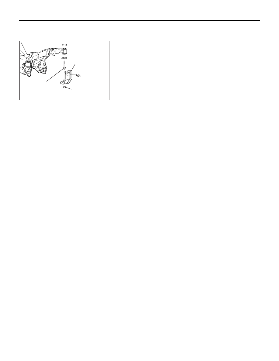
>>C<< CROSSMEMBER STAY/CROSSMEMBER 
NUT INSTALLATION

Ensure that the crossmember mounting bolts have been tight-
ened to specification, and then install the crossmember stay 
with the crossmember nut.

INSPECTION

M1341006900089

• Check the crossmember for cracks or deformation.

• Check all bolts for condition and straightness.

AC306481AC

CROSSMEMBER 
STAY

CROSSMEMBER 
MOUNTING BOLT

CROSSMEMBER 
NUT

SPECIFICATIONS

REAR SUSPENSION

34-27

SPECIFICATIONS

FASTENER TIGHTENING SPECIFICATIONS

M1341012700330

ITEM

SPECIFICATION

Lower arm assembly

Lower arm assembly to crossmember nut

78 

± 7 N⋅m (57 ± 5 ft-lb)

Lower arm assembly to knuckle nut (self-locking nut)

113 

± 12 N⋅m (83 ± 9 ft-lb)

Lower arm assembly to stabilizer bar link assembly nut

40 

± 5 N⋅m (30 ± 3 ft-lb)

Rear suspension crossmember

Crossmember bracket mounting bolt and nut (self-locking 
nut)

83 

± 12 N⋅m (61 ± 9 ft-lb)

Crossmember stay (front) mounting bolt

45 

± 5 N⋅m (34 ± 3 ft-lb)

Crossmember stay (rear) mounting bolt and nut 
(self-locking nut)

83 

± 12 N⋅m (61 ± 9 ft-lb)

Rear suspension crossmember to body bolt

108 

± 17 N⋅m (79 ± 13 ft-lb)

Shock absorber assembly

Shock absorber assembly to body nut

45 

± 5 N⋅m (34 ± 3 ft-lb)

Shock absorber assembly to knuckle bolt

100 

± 10 N⋅m (74 ± 7 ft-lb)

Shock absorber self-locking nut (coil spring nut)

23 

± 2 N⋅m (17 ± 1 ft-lb)

Stabilizer bar

Stabilizer bar link assembly nut

40 

± 5 N⋅m (30 ± 3 ft-lb)

Stabilizer bracket bolt

45 

± 5 N⋅m (34 ± 3 ft-lb)

Toe control arm assembly

Toe control arm assembly to crossmember nut

78 

± 7 N⋅m (57 ± 5 ft-lb)

Toe control arm assembly to knuckle nut (self-locking nut)

66 

± 6 N⋅m (49 ± 4 ft-lb)

Trailing arm assembly

Trailing arm assembly to knuckle nut (self-locking nut)

113 

± 12 N⋅m (83 ± 9 ft-lb)

Trailing arm assembly to trailing arm bracket nut 
(self-locking nut)

113 

± 12 N⋅m (83 ± 9 ft-lb)

Trailing arm bracket to body bolt

105 

± 10 N⋅m (77 ± 7 ft-lb)

Upper arm assembly

Upper arm assembly to crossmember bolt and nut 
(self-locking nut)

113 

± 12 N⋅m (83 ± 9 ft-lb)

Upper arm assembly to knuckle nut (self-locking nut)

113 

± 12 N⋅m (83 ± 9 ft-lb)

SPECIFICATIONS

REAR SUSPENSION

34-28

GENERAL SPECIFICATIONS

M1341000200286

COIL SPRING

SERVICE SPECIFICATIONS

M1341000300421

LUBRICANT

M1341000400183

ITEM

3.8L ENGINE

Wire diameter mm (in)

12.0 (0.47)

Average diameter mm (in)

86.0 

− 112.0 (3.39 − 4.40)

Free length mm (in)

322.0

ITEM

STANDARD VALUE

Camber

−0°50' ± 30' (Difference between 
right and left within 30')

Toe-in mm (in)

± 3 (0.12 ± 0.12)

Toe control arm ball joint turning torque N

⋅m (in-lb)

1.0 

− 2.6 (8.9 − 23)

Stabilizer bar link ball joint breakaway torque N

⋅m (in-lb)

3.4 

− 9.0 (30 − 80)

ITEM

SPECIFIED LUBRICANT

QUANTITY

Toe control arm ball joint (lip and 
inside of dust cover)

Multipurpose grease SAE J310, NLGI 
No.2 or equivalent

± 0.5 g (0.247 ± 0.018 oz)

37-1

GROUP 37

POWER STEERING

CONTENTS

GENERAL DESCRIPTION. . . . . . . . .

37-3

POWER STEERING DIAGNOSIS . . .

37-3

INTRODUCTION TO POWER STEERING 
DIAGNOSIS  . . . . . . . . . . . . . . . . . . . . . . . . 

37-3

POWER STEERING DIAGNOSIS 
TROUBLESHOOTING STRATEGY . . . . . . 

37-3

SYMPTOM CHART. . . . . . . . . . . . . . . . . . . 

37-3

SYMPTOM PROCEDURES . . . . . . . . . . . . 

37-4

SPECIAL TOOLS. . . . . . . . . . . . . . . .

37-13

ON-VEHICLE SERVICE. . . . . . . . . . .

37-14

STEERING WHEEL FREE PLAY CHECK . 

37-14

STEERING ANGLE CHECK . . . . . . . . . . . . 

37-15

TIE ROD END BALL JOINT BREAKAWAY 
TORQUE CHECK . . . . . . . . . . . . . . . . . . . . 

37-15

STATIONARY STEERING EFFORT CHECK

37-16

STEERING WHEEL RETURN TO CENTER 
CHECK . . . . . . . . . . . . . . . . . . . . . . . . . . . . 

37-17

DRIVE BELT TENSION CHECK. . . . . . . . . 

37-17

FLUID LEVEL CHECK  . . . . . . . . . . . . . . . . 

37-17

FLUID REPLACEMENT . . . . . . . . . . . . . . . 

37-18

POWER STEERING SYSTEM AIR 
BLEEDING  . . . . . . . . . . . . . . . . . . . . . . . . . 

37-18

OIL PUMP PRESSURE TEST  . . . . . . . . . . 

37-19

POWER STEERING PRESSURE SWITCH 
CHECK  . . . . . . . . . . . . . . . . . . . . . . . . . . . . 

37-20

TIE ROD END BALL JOINT DUST COVER 
CHECK  . . . . . . . . . . . . . . . . . . . . . . . . . . . . 

37-21

STEERING COLUMN SHAFT ASSEMBLY 
SHOCK ABSORBING MECHANISM CHECK

37-21

STEERING WHEEL*. . . . . . . . . . . . . .

37-23

REMOVAL AND INSTALLATION  . . . . . . . . 

37-23

STEERING SHAFT* . . . . . . . . . . . . . .

37-25

REMOVAL AND INSTALLATION  . . . . . . . . 

37-25

DISASSEMBLY AND ASSEMBLY  . . . . . . . 

37-28

POWER STEERING GEAR BOX AND 
LINKAGE* . . . . . . . . . . . . . . . . . . . . . .

37-30

REMOVAL AND INSTALLATION  . . . . . . . . 

37-30

INSPECTION. . . . . . . . . . . . . . . . . . . . . . . . 

37-37

DISASSEMBLY AND ASSEMBLY  . . . . . . . 

37-38

INSPECTION. . . . . . . . . . . . . . . . . . . . . . . . 

37-42

Continued on next page

WARNINGS REGARDING SERVICING OF SUPPLEMENTAL RESTRAINT SYSTEM (SRS) EQUIPPED VEHICLES

WARNING

Improper service or maintenance of any component of the SRS, or any SRS-related component, can lead to 
personal injury or death to service personnel (from inadvertent firing of the air bag) or to the driver and 
passenger (from rendering the SRS inoperative).

Service or maintenance of any SRS component or SRS-related component must be performed only at an 
authorized MITSUBISHI dealer.

MITSUBISHI dealer personnel must thoroughly review this manual, and especially its GROUP 52B - Supplemental 
Restraint System (SRS) before beginning any service or maintenance of any component of the SRS or any 
SRS-related component.

NOTE
The SRS includes the following components: SRS air bag control unit, SRS warning light, front impact sensors, air bag module,
clock spring, and interconnecting wiring. Other SRS-related components (that may have to be removed/installed in connection
with SRS service or maintenance) are indicated in the table of contents by an asterisk (*).

HOME


Content   ..  848  849  850  851   ..