Mitsubishi 380. Manual - part 845


  Index      Mitsubishi     Mitsubishi 380 - service repair manual 2005 year


Search            


Content   ..  843  844  845  846   ..


Mitsubishi 380. Manual - part 845


ON-VEHICLE SERVICE

REAR SUSPENSION

34-6

ON-VEHICLE SERVICE

REAR WHEEL ALIGNMENT CHECK AND 
ADJUSTMENT

M1341011000394

Measure wheel alignment with an alignment equipment on 
level ground.
The rear suspension and tyres should be serviced to the nor-
mal condition prior to wheel alignment measurement.

.

CAMBER

Standard value:

 0° 50’ ± 30’ (Left/right deviation within 30’) 

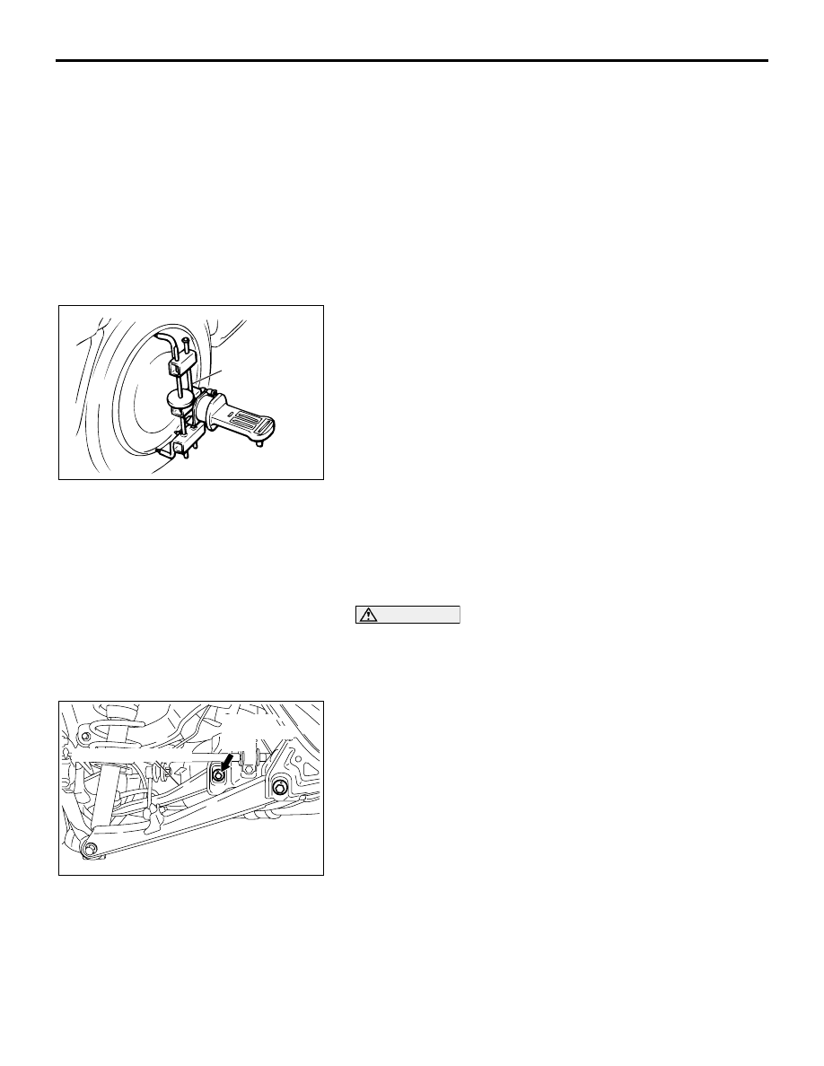
NOTE: For vehicles with aluminum wheels, attach the cam-
ber/caster/kingpin gauge by using a compensator.

.

TOE-IN

Standard value: 3 

± 3 mm (0.12 ± 0.12 inch)

.

If camber and/or toe-in is not within the standard value, adjust 
by the following procedures.

CAUTION

• When adjusting the camber, tighten the lower arm 

assembly and the trailing arm assembly, not the toe 
control arm.

• After adjusting the camber, be sure to adjust the toe.

1. Carry out camber adjustment by turning the camber 

adjusting bolt.

NOTE: 

.

• LH: Clockwise viewed from the rear  () camber

• RH: Clockwise viewed from the rear  (+) camber

• If either the camber or toe is adjusted, both should fluctu-

ate. For the relationship between the two, refer to CAM-
BER AND TOE REFERENCE TABLE (Refer to 

P.34-7

).

AC305848 AB

COMPENSATOR

AC305842

AB

TOE CONTROL ARM

CAMBER 

ADJUSTING 

BOLT

ON-VEHICLE SERVICE

REAR SUSPENSION

34-7

CAUTION

When adjusting the toe, tighten the toe control arm and the 
trailing arm assembly, not the lower arm assembly.
2. Carry out toe adjustment by turning the toe adjusting bolt.

NOTE: 

.

• LH: Clockwise viewed from the rear  Toe-in

• RH: Clockwise viewed from the rear  Toe-out

• If either the camber or toe is adjusted, both should fluctu-

ate. For the relationship between the two, refer to CAM-
BER AND TOE REFERENCE TABLE (Refer to 

P.34-7

).

.

CAMBER AND TOE REFERENCE TABLE

AC305842

AC

LOWER ARM 

ASSEMBLY

TOE ADJUSTING 

BOLT

AC205691AB

1.0

0.8

0.6

0.4

0.2

0

- 0.2

- 0.4

- 0.6

- 0.8

- 1.0

 CAMBER

(DEGREE)

1 DIVISION OF SCALES

LH: CLOCKWISE
RH: COUNTERCLOCKWISE
ON REAR VIEW

LH: CLOCKWISE
RH: COUNTERCLOCKWISE
ON REAR VIEW

0

3.0

- 3.0

- 6.0

- 9.0

- 12.0

- 15.0

6.0

9.0

12.0

15.0

TOE (mm)

→ TOE IN

TOE OUT ←

ADJUSTING TOE 

CONTROL ARM

ADJUSTING  

LOWER ARM

ON-VEHICLE SERVICE

REAR SUSPENSION

34-8

LOWER ARM PILLOW BALL BUSHING END PLAY 
CHECK

M1341016900143

1. Raise the vehicle.

2. Remove the stabilizer bar link assembly from the lower arm 

assembly.

3. Move the lower arm up and down with your hands to check 

for excessive play in the axial direction of the pillow ball 
bushing. If there is excessive play, replace the knuckle 
assembly. (Refer to GROUP 27, Knuckle 

P.27-8

).

4. After inspection, install the stabilizer bar link assembly to the 

lower arm assembly, and tighten the mounting nuts to 40 

± 5 

N

⋅m (30 ± 3 ft-lb).

TOE CONTROL ARM BALL JOINT END PLAY 
CHECK

M1341015800080

1. Raise the vehicle.

2. Move the toe control arm up and down with your hands to 

check for excessive play in the axial direction of the ball 
joint. If there is excessive play, replace the toe control arm 
assembly.

BALL JOINT DUST COVER INSPECTION

M1341012800296

Check the ball joint dust cover of the toe control arm assembly 
and the stabilizer bar link assembly as follows.
1. Check dust cover for cracks or damage by pushing it with 

your finger.

2. If a dust cover is cracked or damaged, replace the toe 

control arm assembly or the stabilizer bar link assembly.

NOTE: Cracks or damage to the dust cover may cause 
damage to the ball joint.

UPPER ARM ASSEMBLY

REAR SUSPENSION

34-9

UPPER ARM ASSEMBLY

REMOVAL AND INSTALLATION

M1341003600216

CAUTION

*

: Indicates parts which should be temporarily tightened, and then fully tightened with the vehicle on 

the ground in an unladen condition.

INSPECTION

M1341003700194

• Check the bushings for wear and deterioration.

• Check the upper arm for bending or breakage.

• Check all bolts for condition and straightness.

Post-installation Operation
• Rear Wheel Alignment Check and Adjustment (Refer to 

P.34-6

).

17DB051A

1

2

3

113 ± 12 N·m*

83 ± 9 ft-lb*

4

N

N

113 ± 12 N·m*

83 ± 9 ft-lb*

4

REMOVAL STEPS

1.

UPPER ARM ASSEMBLY AND 
KNUCKLE CONNECTION

2.

ABS EQUIPMENT BOLT 

3.

UPPER ARM ASSEMBLY

4.

UPPER ARM STOPPER

REMOVAL STEPS (Continued)


Content   ..  843  844  845  846   ..