Mitsubishi 380. Manual - part 794


  Index      Mitsubishi     Mitsubishi 380 - service repair manual 2005 year


Search            


Content   ..  792  793  794  795   ..


Mitsubishi 380. Manual - part 794


SRS AIR BAG DIAGNOSIS

SUPPLEMENTAL RESTRAINT SYSTEM (SRS)

52B-100

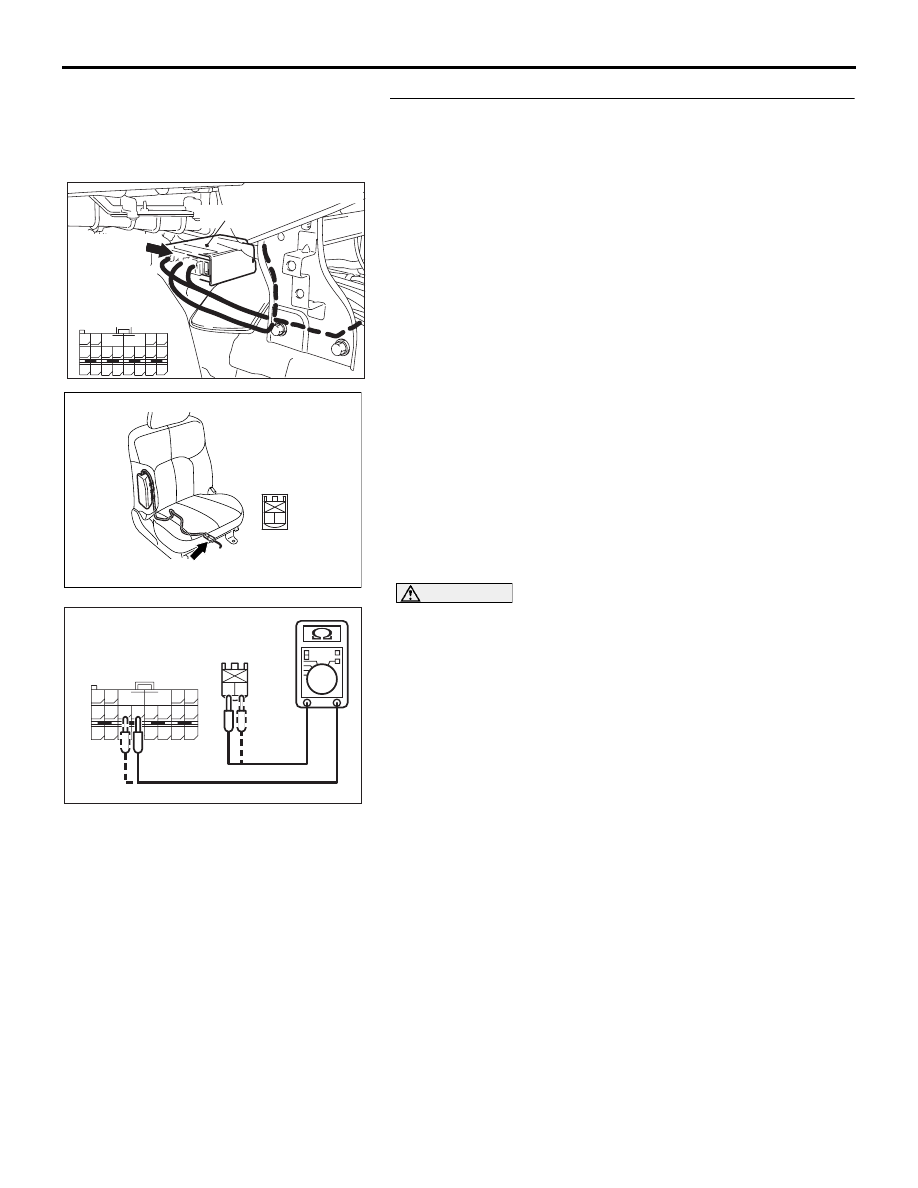
STEP 4. Check the harness for open circuit between 
SRS-ECU connector D-26 (terminal No.57 and 58) and the 
side-airbag module (RH) connector D-32 (terminal No.1 
and 2).
(1) Disconnect SRS-ECU connector D-26 and side-airbag 

module (RH) connector D-32.

CAUTION

Do not insert a test probe into the terminal from its front 
side directly, as the connector contact pressure may be 
weakened.
(2) Check for continuity between the following terminals. It 

should be less than 2 ohms.

• SRS-ECU connector D-26 (terminal No.57) and the 

side-airbag module (RH) connector D-32 (terminal No.2)

• SRS-ECU connector D-26 (terminal No.58) and the 

side-airbag module (RH) connector D-32 (terminal No.1)

Q: Does continuity exist?

YES : Erase the diagnostic trouble code memory, and check 

the diagnostic trouble code. If DTC B1421 sets, 
replace the SRS-ECU (Refer to 

P.52B-234

). Then go 

to Step 5.

NO :  Replace the harness wires between SRS-ECU 

connector D-26 and side-airbag module (RH) 
connector D-32. Then go to Step 5.

AC307779

D-32 (R)

AD

2

1

HARNESS SIDE
CONNECTOR
(REAR VIEW)

CONNECTOR : D-32

24DB063A

CONNECTOR: D-26

SRS-ECU

63

55

51

69

61

66

58

65

64

5657

68

60

67

59

70

62

53

52 B A

54

D-26  (Y)

D-26 FLOOR

HARNESS

CONNECTOR

(REAR VIEW)

24DB071A

1 2

63

55

51

69

61

66

58

65

64

5657

68

60

67

59

70

62

53

52 B A

54

D-26 FLOOR 

HARNESS SIDE

CONNECTOR

(REAR VIEW)

D-32 

HARNESS SIDE

CONNECTOR 

(REAR VIEW)

SRS AIR BAG DIAGNOSIS

SUPPLEMENTAL RESTRAINT SYSTEM (SRS)

52B-101

STEP 5. Recheck for diagnostic trouble code.
Check again if the DTC is set.
(1) Erase the DTC.
(2) Turn the ignition switch to the "ON" position.
(3) Check if the DTC is set.
(4) Turn the ignition switch to the "LOCK" (OFF) position.

Q: Is DTC B1421 set?

YES : Return to Step 1. 
NO :  The procedure is complete.

00DB076A

MB991910

DATA LINK

CONNECTOR

MB991824

MB991827

SRS AIR BAG DIAGNOSIS

SUPPLEMENTAL RESTRAINT SYSTEM (SRS)

52B-102

DTC B1422: Side-Airbag Module (RH) (Squib) System Fault Power Supply Circuit (Short-Circuited to 
Power Supply)

CAUTION

If DTC B1422 is set in the combination meter, 
always diagnose the CAN bus lines.

.

CIRCUIT OPERATION

• The SRS-ECU judges how severe a collision is 

by detecting signals from the left and right side 
impact sensors. If the impact is over a predeter-
mined level, the SRS-ECU sends an ignition sig-
nal. At this time, if the side-airbag safing 
G-sensor is on, the SRS side-airbag will inflate.

• The ignition signal is input to the side-airbag 

module to inflate the side-airbag.

.

DTC SET CONDITIONS

This DTC is set if there is abnormal resistance 
between the input terminals of the side-airbag mod-
ule (RH) (squib).

.

TROUBLESHOOTING HINTS

• Damaged wiring harnesses or connectors

• Short to the power supply in the side-airbag mod-

ule (RH) (squib) harness

• Malfunction of the SRS-ECU

• Refer to circuit diagrams GROUP-

90

• Refer to configuration diagrams GROUP-

80

.

DIAGNOSIS

Required Special Tools:

•  MB991958: diagnostic tool (MUT-III Sub Assembly)

• MB991824: Vehicle Communication Interface (V.C.I.)

• MB991827: MUT-III USB Cable

• MB991910: MUT-III Main Harness A (Vehicles with CAN 

communication system)

• MB991865: Dummy resistor

• MB991866: Resistor harness

24DB063A

CONNECTOR: D-26

SRS-ECU

63

55

51

69

61

66

58

65

64

5657

68

60

67

59

70

62

53

52 B A

54

D-26  (Y)

D-26 FLOOR

HARNESS

CONNECTOR

(REAR VIEW)

AC307779

D-32 (R)

AC

CONNECTOR : D-32

SRS AIR BAG DIAGNOSIS

SUPPLEMENTAL RESTRAINT SYSTEM (SRS)

52B-103

STEP 1. Using diagnostic tool MB991958, diagnose the 
CAN bus line.

CAUTION

To prevent damage to diagnostic tool MB991958, always 
turn the ignition switch to the "LOCK" (OFF) position 
before connecting or disconnecting diagnostic tool 
MB991958.
(1) Connect diagnostic tool MB991958. Refer to "How to 

connect the diagnostic tool 

P.52B-19

."

(2) Turn the ignition switch to "ON" position.
(3) Diagnose the CAN bus line.
(4) Turn the ignition switch to the "LOCK" (OFF) position.

Q: Is the check result satisfactory?

YES : Go to Step 2
NO :  Repair the CAN bus lines (Refer to GROUP 54C, 

Diagnosis-Can Bus Diagnostic Chart ).

STEP 2. Recheck for diagnostic trouble code.
Check again if the DTC is set.
(1) Erase the DTC.
(2) Turn the ignition switch to "ON" position.
(3) Check if the DTC is set.
(4) Turn the ignition switch to the "LOCK" (OFF) position.

Q: Is the DTC set?

YES : Go to Step 3.
NO :  There is an intermittent malfunction such as poor 

engaged connector(s) or open circuit (Refer to 
GROUP 00, How to Use Troubleshooting/Inspection 
Service Points 

− How to Cope with Intermittent 

Malfunctions ).

00DB076A

MB991910

DATA LINK

CONNECTOR

MB991824

MB991827

00DB076A

MB991910

DATA LINK

CONNECTOR

MB991824

MB991827


Content   ..  792  793  794  795   ..