Mitsubishi 380. Manual - part 785


  Index      Mitsubishi     Mitsubishi 380 - service repair manual 2005 year


Search            


Content   ..  783  784  785  786   ..


Mitsubishi 380. Manual - part 785


SRS AIR BAG DIAGNOSIS

SUPPLEMENTAL RESTRAINT SYSTEM (SRS)

52B-64

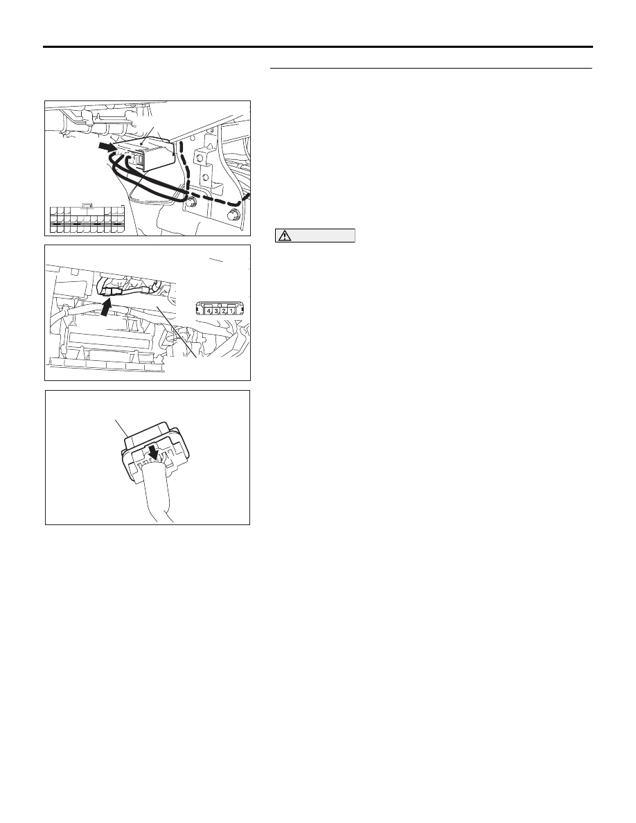
STEP 7. Check the passenger’s air bag module circuit at 
SRS-ECU connector C-121.
(1) Disconnect SRS-ECU connector C-121.

DANGER

To prevent the air bag from deploying unintentionally, 
disconnect the passenger’s air bag module connec-
tor C-110 to short the squib circuit.

(2) Disconnect the passenger's air bag module connector 

C-110.

(3) Slide the outer housing of the clock spring side of driver’s 

air bag module connector C-110 in the arrow direction 
shown, and disconnect the connector.

24DB062A

CONNECTOR: C-121

C-121 (Y)

SRS-ECU

42

31

38

27

21

41

28

39

22

30

25

47

36

33

44

34

45

37

48

26

29

23

40

32

43

35

46

24

B

A

C-121

INSTRUMENT

HARNESS

CONNECTOR

(REAR VIEW)

52DB018A

C-110 (Y)

FRONT DECK
CROSSMEMBER

CONNECTOR: C-110

HARNESS SIDE 
CONNECTOR
(REAR VIEW)

AC306561AD

OUTER HOUSING OF THE PASSENGER'S 
AIR BAG MODULE CONNECTOR C-110

SRS AIR BAG DIAGNOSIS

SUPPLEMENTAL RESTRAINT SYSTEM (SRS)

52B-65

CAUTION

Insert an insulator such as a cable tie to a depth of 4mm 
(0.16 inch) or more, otherwise the short spring will not be 
released.
(4) Insert a cable tie [3 mm (0.12 inch) wide, 0.5 mm (0.02 inch) 

thick] between terminals 37 and 36 , and the short spring to 
release the short spring.

CAUTION

Do not insert a test probe into the terminal from its front 
side directly as the connector contact pressure may be 
weakened.
(5) Check for continuity between C-121 harness side connector 

terminals 37 and 36 .
It should be open circuit.

Q: Does continuity exist?

YES : Go to Step 8.
NO :  Erase the diagnostic trouble code memory, and check 

the diagnostic trouble code. If DTC B1410  set, 
replace the SRS-ECU (Refer to 

P.52B-234

). Then go 

to Step 9.

STEP 8. Check the harness for short circuit between 
SRS-ECU connector C-121 (terminal No.37 and 36 ) and 
passenger's air bag module connector C-110 (terminal 
No.1 and 2 ).
Q: Are harness wires between SRS-ECU connector C-121 

(terminal No.37 and 36 ) and passenger's air bag module 
connector C-110 (terminal No.1 and 2 ) in good 
condition?
YES : 
Go to Step 9.
NO :  Replace the harness wires between SRS-ECU 

connector C-121 and passenger’s air bag module 
connector C-110. Then go to Step 9.

AC308142

SECTION
A - A

C-121 HARNESS SIDE 
CONNECTOR
(FRONT VIEW)

CABLE TIE

SHORT SPRING

4 mm OR MORE

TERMINAL

AB

<1ST SQUIB>

A

A

AC308143

SECTION
A - A

C-121 HARNESS SIDE 
CONNECTOR
(FRONT VIEW)

CABLE TIE

SHORT SPRING

4 mm OR MORE

TERMINAL

AB

<2ND SQUIB>

A

A

52DB018A

C-110 (Y)

FRONT DECK
CROSSMEMBER

CONNECTOR: C-110

HARNESS SIDE 
CONNECTOR
(REAR VIEW)

24DB062A

CONNECTOR: C-121

C-121 (Y)

SRS-ECU

42

31

38

27

21

41

28

39

22

30

25

47

36

33

44

34

45

37

48

26

29

23

40

32

43

35

46

24

B

A

C-121

INSTRUMENT

HARNESS

CONNECTOR

(REAR VIEW)

SRS AIR BAG DIAGNOSIS

SUPPLEMENTAL RESTRAINT SYSTEM (SRS)

52B-66

STEP 9. Check for diagnostic trouble code.
Check again if the DTC is set.
(1) Erase the DTC.
(2) Turn the ignition switch to the "ON" position.
(3) Check if the DTC is set.
(4) Turn the ignition switch to the "LOCK" (OFF) position.

Q: Is DTC B1410  set?

YES : Return to Step 1.
NO :  The procedure is complete.

00DB076A

MB991910

DATA LINK

CONNECTOR

MB991824

MB991827

SRS AIR BAG DIAGNOSIS

SUPPLEMENTAL RESTRAINT SYSTEM (SRS)

52B-67

DTC B1411: Passenger’s (Front) Air Bag Module (1st Squib) System Fault 2 (Open in the Squib 
Circuit)

CAUTION

If DTC B1411  is set in the SRS-ECU, always diag-
nose the CAN main bus line.

.

CIRCUIT OPERATION

• The SRS-ECU judges how severe a collision is 

by detecting signals from the front impact sensors 
and the front air bag analog G-sensor. If the 
impact is over a predetermined level, the 
SRS-ECU sends an ignition signal. At this time, if 
the front air bag safing G-sensor is on, the SRS 
air bag will inflate. 

• The ignition signal is input to the air bag module 

via the clock spring to inflate the air bag.

.

DTC SET CONDITIONS

This DTC is set if there is abnormal resistance 
between the input terminals of the passenger’s air 
bag module (squib). However, if no DTC reset, the 
SRS warning light will be switched off (DTC will be 
retained). 

.

TROUBLESHOOTING HINTS

• Open circuit in the passenger's air bag module 

(squib) circuit

• Improper connector contact

• Malfunction of the SRS-ECU

• Refer to circuit diagrams GROUP-

90

• Refer to configuration diagrams GROUP-

80

.

DIAGNOSIS

Required Special Tools:

• MB991958: diagnostic tool (MUT-III Sub Assembly)

• MB991824: Vehicle Communication Interface (V.C.I.)

• MB991827: MUT-III USB Cable

• MB991910: MUT-III Main Harness A (Vehicles with CAN 

Communication System)

• MB991865: Dummy resister

• MB991866: Resistor harness

52DB017A

C-110 (Y)

FRONT DECK
CROSSMEMBER

CONNECTOR: C-110

24DB062A

CONNECTOR: C-121

C-121 (Y)

SRS-ECU

42

31

38

27

21

41

28

39

22

30

25

47

36

33

44

34

45

37

48

26

29

23

40

32

43

35

46

24

B

A

C-121

INSTRUMENT

HARNESS

CONNECTOR

(REAR VIEW)


Content   ..  783  784  785  786   ..